Joint video monitoring method and system thereof

A technology for video surveillance and monitoring targets, applied in CCTV systems and other directions, can solve the problems of slow switching speed, inconvenient control, cumbersome switching scenes, etc., and achieve the effects of low switching cost, easy control, and fast switching speed.

Inactive Publication Date: 2010-12-22
ZTE CORP
View PDF3 Cites 57 Cited by
  • Summary
  • Abstract
  • Description
  • Claims
  • Application Information

AI Technical Summary

Problems solved by technology

[0006] In order to solve the problems of slow switching speed, cumbersome scene switching, inconvenient control, and inability to jointly monitor a specific monitoring target

Method used


Image

  • Joint video monitoring method and system thereof
  • Joint video monitoring method and system thereof
  • Joint video monitoring method and system thereof

Examples


Embodiment Construction

[0034] In order to make the technical problems, technical solutions and beneficial effects to be solved by the present invention clearer and clearer, the present invention will be further described in detail below in conjunction with the accompanying drawings and embodiments. It should be understood that the specific embodiments described here are only used to explain the present invention, not to limit the present invention.

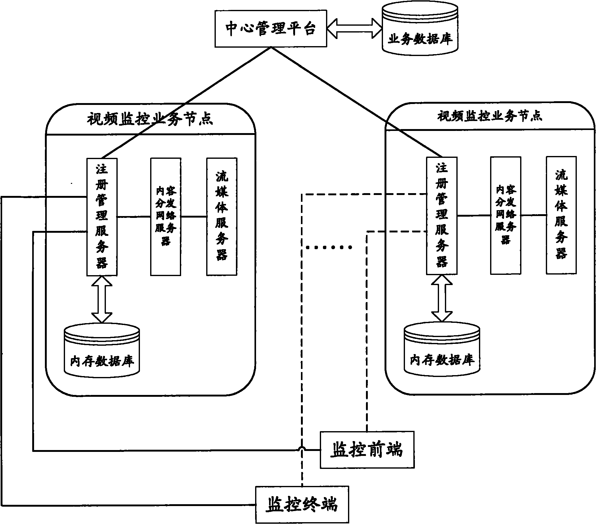
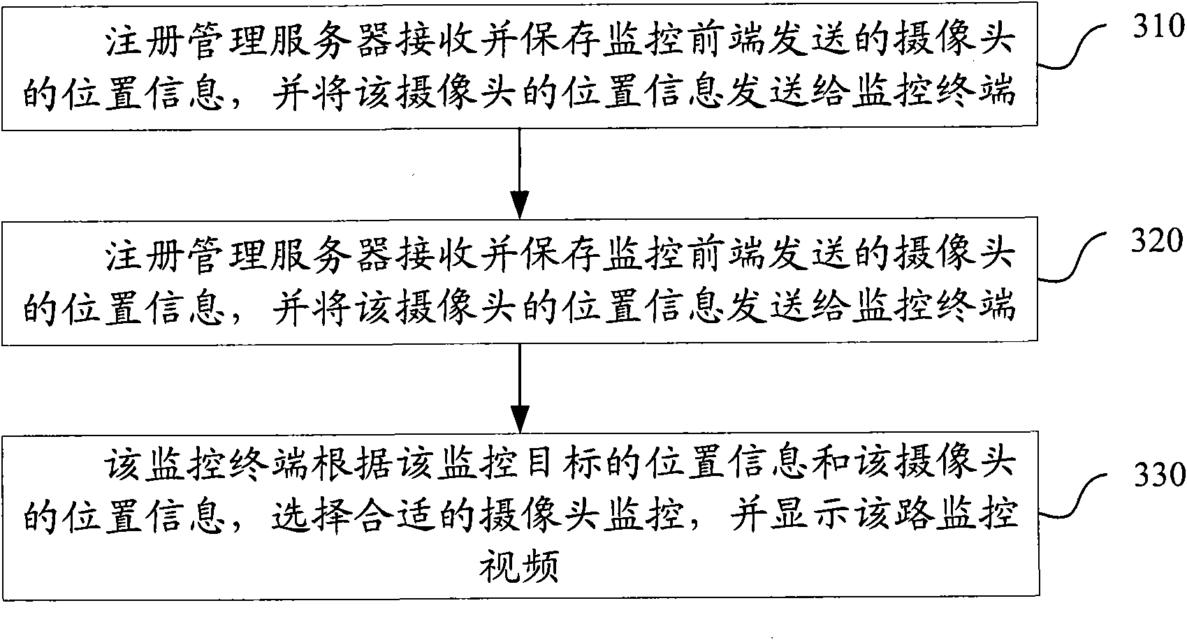
[0035] The embodiment of the present invention provides a method for joint video monitoring, such as image 3 shown, including:

[0036] 310. The registration management server receives and saves the location information of the camera sent by the monitoring front end, and sends the location information of the camera to the monitoring terminal;

[0037] 320. The registration management server receives the location information of the monitoring object sent by the navigation transponder carried on the monitoring object, and sends the location information ...


PUM


Abstract

The invention discloses a joint video monitoring method and a system thereof, belonging to the video monitoring field. The method comprises the following steps: a registration management server receives and stores position information of cameras sent by a monitoring front end, and sends the position information of the cameras to a monitoring terminal; the registration management server receives position information of a monitoring target sent by a navigation forwarder carried on the monitoring target and sends the position information of the monitoring target to the monitoring terminal; and the monitoring terminal selects proper cameras for monitoring according to the position information of the monitoring target and the position information of the cameras, and displays the monitoring video. The system comprises the registration management server, the monitoring terminal, the monitoring front end and the navigation forwarder carried on the monitoring target. The invention can easily control lenses of the cameras, automatically switch scenes during the whole monitoring process at high speed and low cost, and unite a plurality of cameras to jointly monitor the monitoring target.

Description

technical field [0001] The invention relates to the field of video monitoring, in particular to a joint video monitoring method and system. Background technique [0002] Video surveillance systems are used more and more widely. The system optimizes and combines multimedia video technology, computer network technology, industrial control technology and artificial intelligence technology to realize system networking and intelligent management, so that enterprises or individual users can use mobile phones or computers to log in no matter where they are. The Internet is connected to the remote multimedia terminal products to realize real-time image and sound transmission. [0003] In the existing environment, customers are no longer satisfied with monitoring a fixed location with a single camera, and sometimes require multiple cameras to be combined for comprehensive tracking and monitoring. [0004] The structure diagram of the current video surveillance terminal system is as...

Claims


Application Information

Patent Timeline
IPC IPC(8): H04N7/18
Inventor 屈小刚
Owner ZTE CORP
Why Eureka
Try Eureka