Nozzle for a liquid-cooled plasma burner, arrangement thereof with a nozzle cap, and liquid-cooled plasma burner comprising such an arrangement

a technology of liquid-cooled plasma burner and nozzle, which is applied in the direction of plasma welding apparatus, plasma technique, manufacturing tools, etc., can solve the problems of repeated overheating in the vicinity and require a greater amount of cooling effort, so as to improve cooling, enhance the flow rate of coolant in the vicinity of the nozzle bore, and increase the service life of the nozzle

Active Publication Date: 2013-11-05
KJELLBERG FINSTERWALDE PLASMA & MASCH GMBH
View PDF23 Cites 28 Cited by
  • Summary
  • Abstract
  • Description
  • Claims
  • Application Information

AI Technical Summary

Benefits of technology

[0042]The preferred embodiments of the invention are based on the surprising realization that by providing at least one deflection section, the nozzle is supplied in a simple manner with coolant flowing round it more uniformly than hitherto, which also means that coolant reaches the vicinity of the nozzle bore to a greater extent and/or that the flow rate of the coolant in the vicinity of the nozzle bore is enhanced. No additional component is needed to improve the cooling in order to increase the service life of the

Problems solved by technology

Nevertheless, overheating is repeatedly found in the vicinity of the nozzle channel.
This arrangement for its part suffers from the disa

Method used


Image

  • Nozzle for a liquid-cooled plasma burner, arrangement thereof with a nozzle cap, and liquid-cooled plasma burner comprising such an arrangement
  • Nozzle for a liquid-cooled plasma burner, arrangement thereof with a nozzle cap, and liquid-cooled plasma burner comprising such an arrangement
  • Nozzle for a liquid-cooled plasma burner, arrangement thereof with a nozzle cap, and liquid-cooled plasma burner comprising such an arrangement

Examples


Embodiment Construction

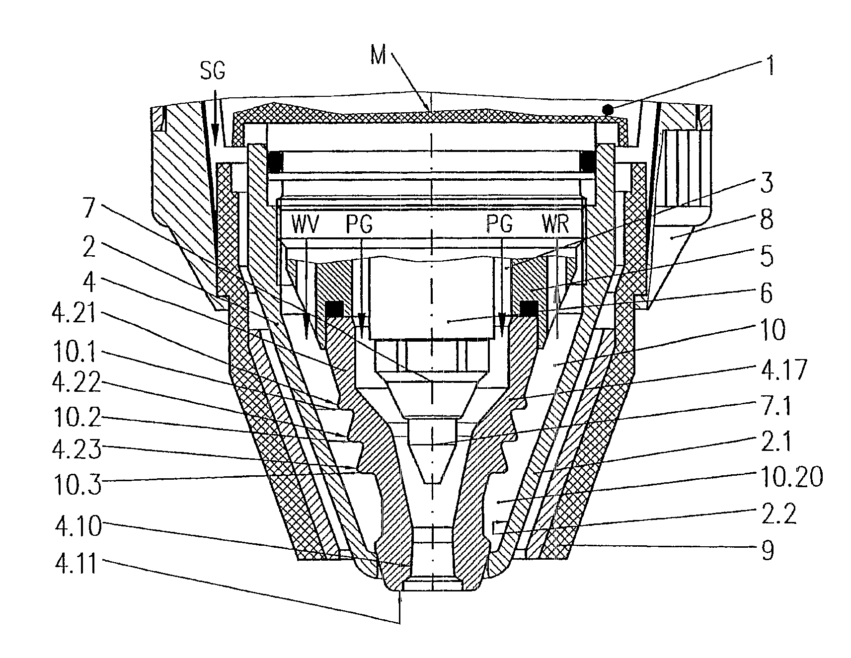
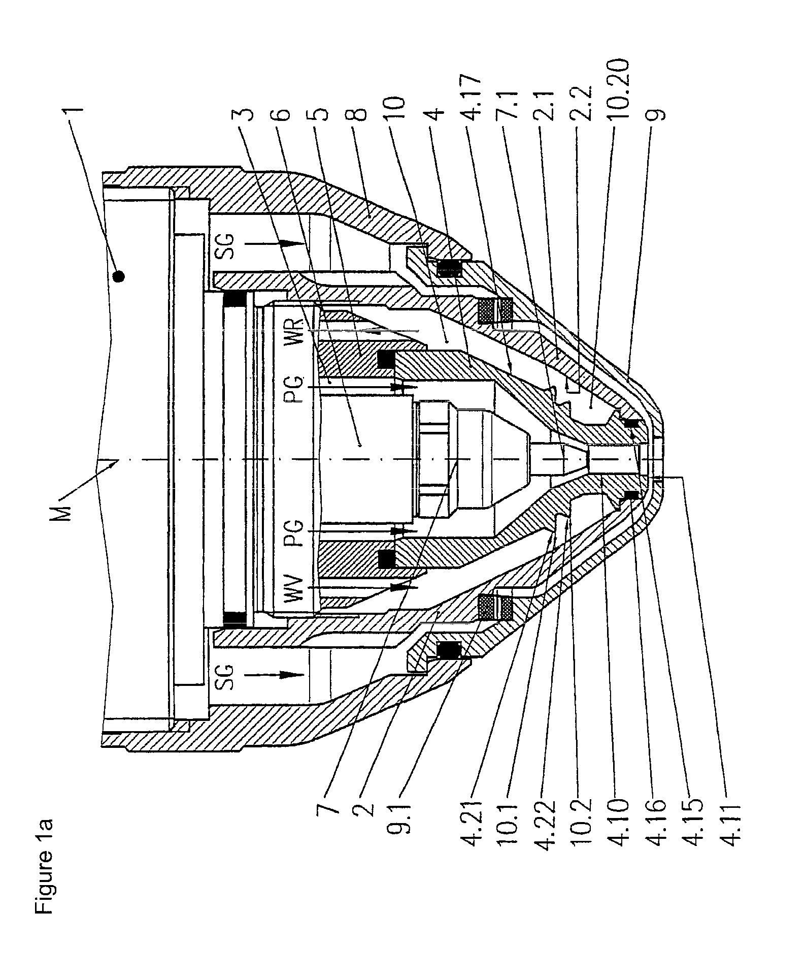
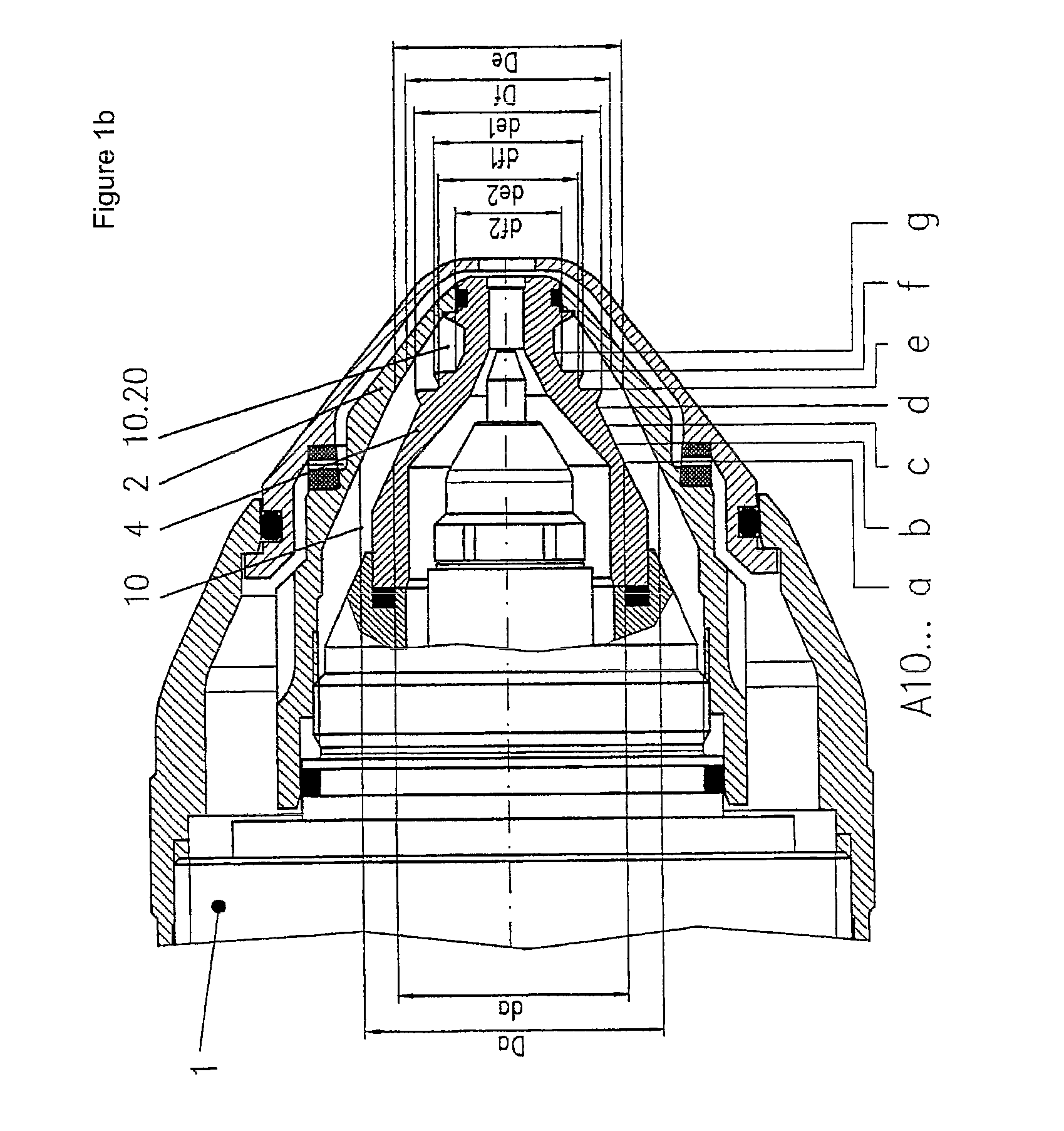
[0063]The plasma burner head 1 shown in FIGS. 1a, 1b and 2 has an electrode quill 6, with which it holds an electrode 7 with an electrode insert 7.1—via a thread (not shown) in the present case. The electrode 7 is designed as an electrode holder with a pointed electrode insert 7.1 made of tungsten. For the plasma burner, it is, for example, possible to use an argon / hydrogen mixture as the plasma gas. A nozzle 4 is held by a cylindrical nozzle bracket 5. A nozzle cap 2, which is attached to the plasma burner head 1 by means of a thread, immobilises the nozzle 4 and forms a coolant chamber 10 with it. The coolant chamber 10 is sealed between the nozzle 4 and the nozzle cap 2 by a seal implemented with an O-ring 4.16, which is located in a groove 4.15 in the nozzle 4. The nozzle 4 has a first section 4.17, the outer surface 4.2 of which tapers in the shape of a cone in the direction of the nozzle tip at an angle α, except for two deflection sections 4.21 and 4.22 which extend in the sh...


PUM

PropertyMeasurementUnit
Lengthaaaaaaaaaa
Angleaaaaaaaaaa
Angleaaaaaaaaaa

Abstract

The invention relates to a liquid-cooled plasma burner, comprising a nozzle bore for the plasma gas jet to exit at a nozzle tip and a first section whose outer surface gradually tapers in the shape of a cone at an angle α in the direction of the nozzle tip, except for at least one deflection section that extends in the shape of a cone at an angle β in the direction of the nozzle tip. The invention also relates to an arrangement thereof with a nozzle cap and to a plasma burner comprising such an arrangement.

Description

[0001]The present invention relates to plasma burners. More particularly, the present invention relates to a nozzle and a nozzle cap for liquid-cooled plasma burners.BACKGROUND[0002]A plasma is the term used for an electrically conductive gas consisting of positive and negative ions, electrons and excited and neutral atoms and molecules which is heated thermalbly to a high temperature.[0003]Various gases are used as plasma gases, such as mono-atomic argon and / or the diatomic gases hydrogen, nitrogen, oxygen or air. These gases are ionised and dissociated by the energy of an electric arc. The electric arc is constricted by a nozzle and is then referred to as a plasma jet.[0004]The parameters of the plasma jet can be heavily influenced by the design of the nozzle and the electrode. These parameters of the plasma jet are, for example, the diameter of the jet, the temperature, the energy density and the flow rate of the gas.[0005]In plasma cutting, for example, the plasma is constricted...

Claims


Application Information

Patent Timeline
IPC IPC(8): B23K10/00
CPCH05H1/34H05H1/28H05H2001/3478H05H1/3478
Inventor LAURISCH, FRANKKRINK, VOLKERGRUNDKE, TIMOREINKE, RALF-PETER
Owner KJELLBERG FINSTERWALDE PLASMA & MASCH GMBH
Why Eureka
Try Eureka