
Circuit Branch Measuring System

Inactive Publication Date: 2015-07-02
REMAKE ELECTRIC EHF
View PDF4 Cites 2 Cited by
  • Summary
  • Abstract
  • Description
  • Claims
  • Application Information

AI Technical Summary

Benefits of technology

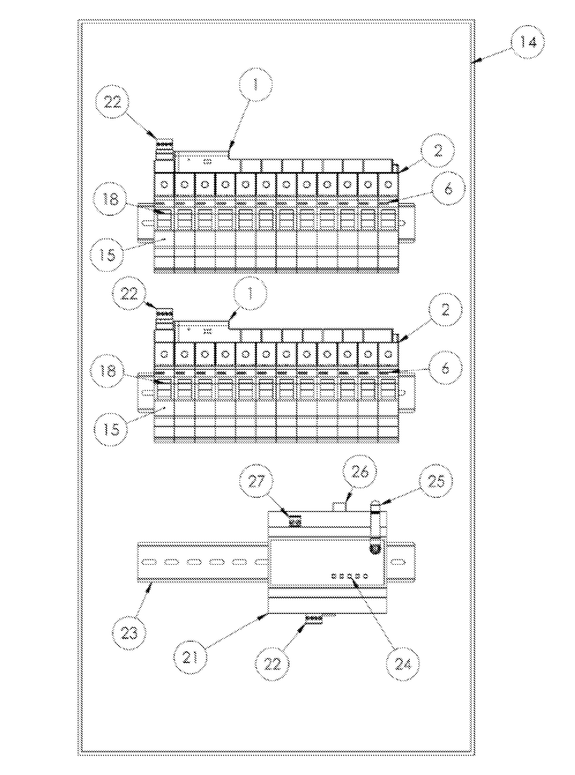
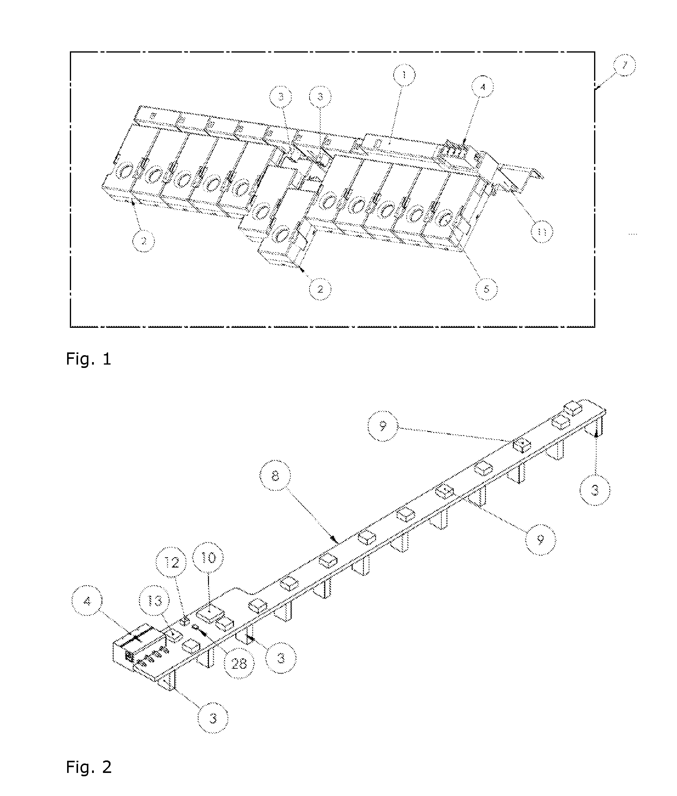
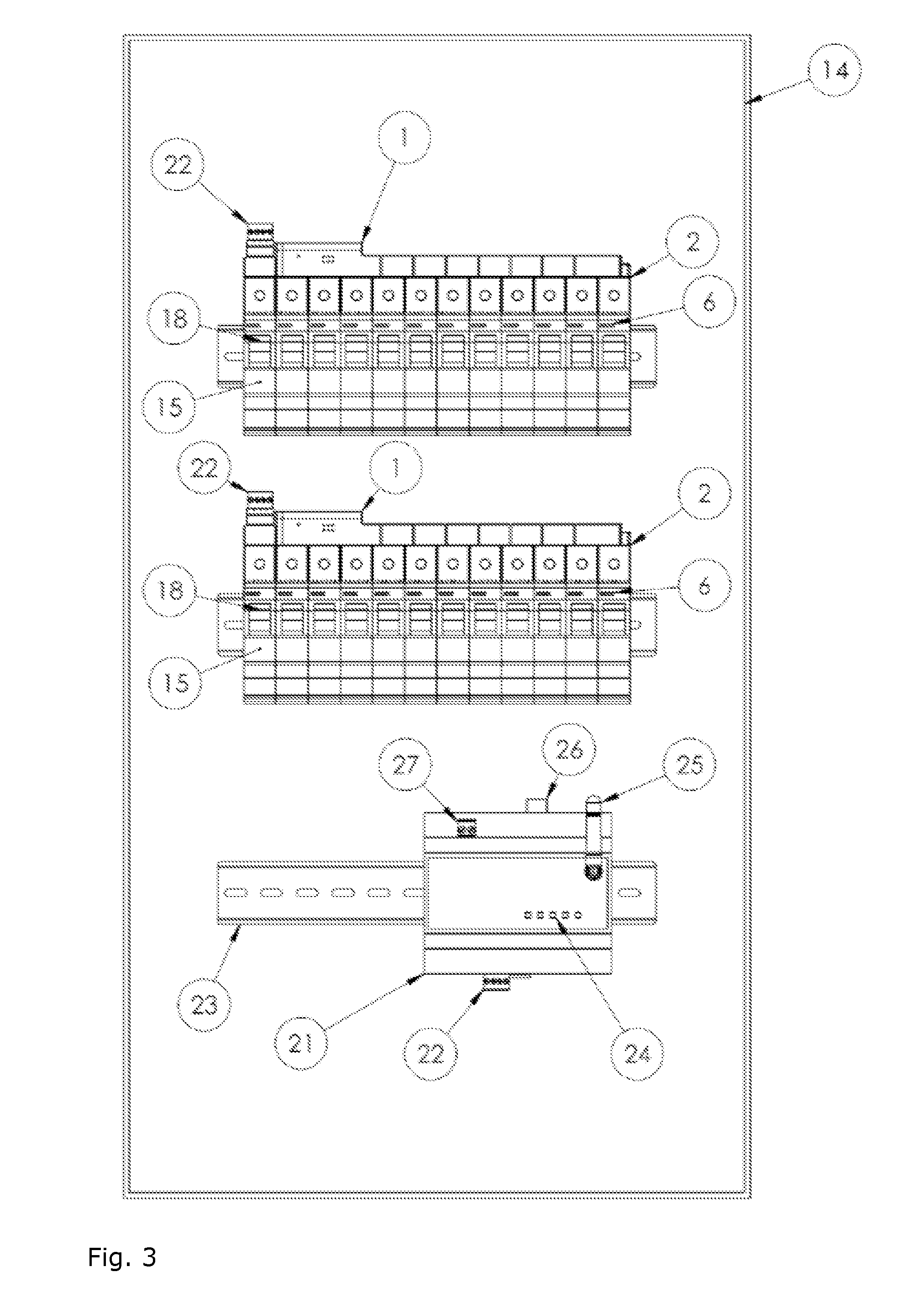
This patent describes a device and system for measuring electricity in a circuit panel. The device contains a current sensor module that attaches to a larger device called the primary unit. The primary unit uses a microprocessor to collect and process measurement signals. It also has a communication driver to transmit the data to an external device. The current sensor module contains a current sensor that measures the electricity in a circuit branch. The device also has an identification microchip to uniquely associate the current sensor with a circuit breaker. The system also includes a monitoring device to receive the data from the primary unit. The current sensor modules are detachable from the primary unit and can be used to measure several circuit branches. The current sensors can be current transformers, split-core current transformers, or Hall effect sensors, and they are powered by the primary unit. Overall, this patent provides a reliable and efficient way to measure electricity in a circuit panel.

Problems solved by technology

The problem with this system is the size and limited communication abilities,
This is especially disadvantageous as distribution panels are typically dense with separate conductors related to each circuit breaker, neutral and ground connections of each circuit branch, including conductors for the Main breaker and other protection devices associated to an electrical installation.
As circuit breakers by an installation in distribution cabinets are typically numerous and positioned in line and relatively close to one another this arrangement is also costly and impractical by installation.
This is especially disadvantageous due to dimensional restrains in electrical distribution panels around circuit breakers and conductor connections thereto, as each the individual current sensor module is linked to each the circuit breaker by a separate conductor.
This is disadvantageous as powering the current sensors from the circuit line may increase the power of the circuit line and thus affect the desired measurement.
By the devices a professional is limited to measuring one circuit branch at a time.
This is particularly disadvantageous as it is a very time consuming process to measure numerous circuits and difficult to get a synchronised reading from numerous circuit branches for making analysis and comparison.

Method used


Image

  • Circuit Branch Measuring System
  • Circuit Branch Measuring System
  • Circuit Branch Measuring System

Examples


Embodiment Construction

[0015]The following embodiments and definitions all relate to the devices and the system of the invention.

[0016]In an embodiment of the present invention the current sensor modules are detachable from the current measurement and data transmitting device.

[0017]In an embodiment of the present invention the current sensor is selected from, but not limited to a current transformer, split-core current transformer or a Hall effect sensor. Furthermore, the current sensor module may be operated and powered by the current measurement and data transmitting device.

[0018]In an embodiment of the present invention the input / output interface of the current measurement and data transmitting device has a Wi-Fi module.

[0019]In an embodiment of the present invention the current sensor module comprises a visual indicator. The visual indicator may be detachable from the current sensor module. Furthermore, the visual indicator comprises at least one LED to indicate a current state, identity process, erro...


PUM


Abstract

A circuit branch measurement system and device are provided for detecting electrical current by circuit branches in an electrical distribution panel. The circuit branch measurement device consist of a current measurement and data transmitting device which is electrically and mechanically connected current sensor modules. The system comprises an identification device to associate each attached current sensor module with a unique identification number and a communication driver to transmit the collective data from the system to a monitoring device.

Description

FIELD OF THE INVENTION[0001]The present invention relates generally to power measurement systems, and more particularly to a circuit branch measuring system by a current measurement and data transmission device comprising sensor modules for detecting current in an electrical power system.BACKGROUND OF THE INVENTION[0002]Measurement devices for measuring a current flowing through a conductor by a circuit breaker are known in the art to be auxiliary devices which are attached to circuit breakers for measuring distinct currents. In practice these devices generally include sensing means for detecting a current, a micro-processor for processing the signal from the sensing means, and output for transmitting the processed data signal from the microprocessor including an input for powering the microprocessor from an external source. An example of such a device is described in UK patent application GB 2,450,426 and in EP 2,282,321. Furthermore, circuit breakers comprising integrated current ...

Claims


Application Information

Patent Timeline
IPC IPC(8): G01R19/00
CPCG01R19/0092G01R21/133G01R22/063H01H71/125H02H1/0038
Inventor AXELSSON, HALLDOREINARSSON, RAGNARJONSSON, BJARNI MALMQUISTPALSSON, KARLJONSSON, HILMIR INGI
Owner REMAKE ELECTRIC EHF
Learn More