Boat Anchor and Method of Making the Same

a technology for anchors and boats, applied in the direction of superimposed coating process, liquid/solution decomposition chemical coating, vessel construction, etc., can solve the problems of unrestrained movement and bending of flexible tines, point to quickly fail under extended use, etc., to achieve quick and easy deployment, easy to retrieve, and minimal effort

Inactive Publication Date: 2015-07-09
SAMUELS GEOFF
View PDF13 Cites 2 Cited by
  • Summary
  • Abstract
  • Description
  • Claims
  • Application Information

AI Technical Summary

Benefits of technology

[0007]The present invention provides a lightweight anchor that operates by gripping engagement with the bottom surface such that it can be used with many commonly encountered surface conditions. The anchor disclosed herein may be quickly and easily deployed, because it is lightweight the user can lift and throw it with minimal effort. The disclosed anchor is also easily retrieved, even under conditions that would present substantial difficulty with a conventional anchor. The anchor disclosed herein further includes a protective coating which provides greater strength and durability for the anchor, and in particular for the flexible tines.
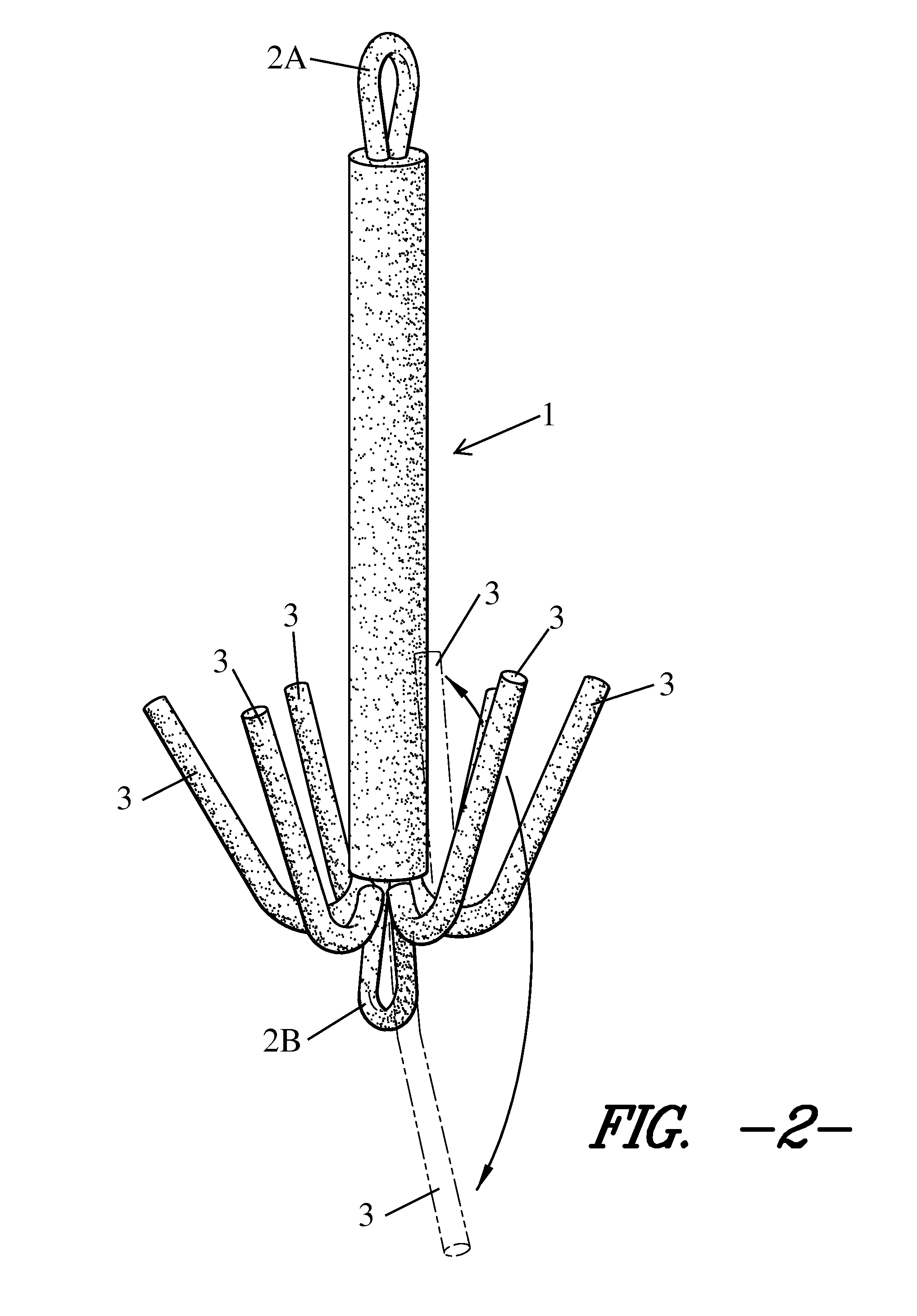
[0008]In contrast with heavyweight anchors most commonly used today, the anchor of the present invention works by hooking into or otherwise engaging the bottom surface of the body of water in which the boat is to be anchored. The anchor of the present invention may therefore be easily retrieved, firstly because it is light in weight, and secondly because its tines will flex under sufficient force to unhook or disengage from the bottom surface. Once the anchor is retrieved, the flexible tines can easily be bent back to their operative configuration to engage with the bottom surface again when the anchor is next deployed. Additionally, the flexible tines are unrestrained in their movement and bending. This allows the tines to freely flex as needed to engage any type of bottom surface. Moreover, the unconstrained bending of the flexible tines allows the bending stress incurred when the tines flex during disengagement from the bottom to be distributed along the length of each tine as it bends, avoiding any fulcrum points so that the bending stress ideally has no concentration point, or at least does not concentrate at the same point repeatedly, which would cause that point to quickly fail under extended use. The protective coating reinforces the flexible tines throughout repeated cycles of bending and re-shaping, which increases the durability and usable life of the anchor.
[0009]The ease of retrieval of the disclosed anchor can be enhanced with an additional quick-release feature. In one embodiment, the present invention includes a second attachment point on the bottom end of the main body. The quick-release feature is implemented by rigging the anchor using the second, bottom attachment point as the primary rode attachment point, e.g., by tying a rope or by securely connecting a chain to the bottom attachment point, and the top attachment point is used as a temporary attachment point, e.g., by attaching the rope or chain thereto with a cable tie, also known as a zip tie. When the anchor is deployed, the temporary rode attachment at the top attachment point will be operative. When sufficient force is applied to break the temporary connection at the top attachment point, the anchor will be inverted and disengage from the surface, allowing for quick and easy retrieval of the anchor.

Problems solved by technology

Additionally, the flexible tines are unrestrained in their movement and bending.
Moreover, the unconstrained bending of the flexible tines allows the bending stress incurred when the tines flex during disengagement from the bottom to be distributed along the length of each tine as it bends, avoiding any fulcrum points so that the bending stress ideally has no concentration point, or at least does not concentrate at the same point repeatedly, which would cause that point to quickly fail under extended use.

Method used


Image

  • Boat Anchor and Method of Making the Same
  • Boat Anchor and Method of Making the Same
  • Boat Anchor and Method of Making the Same

Examples


Embodiment Construction

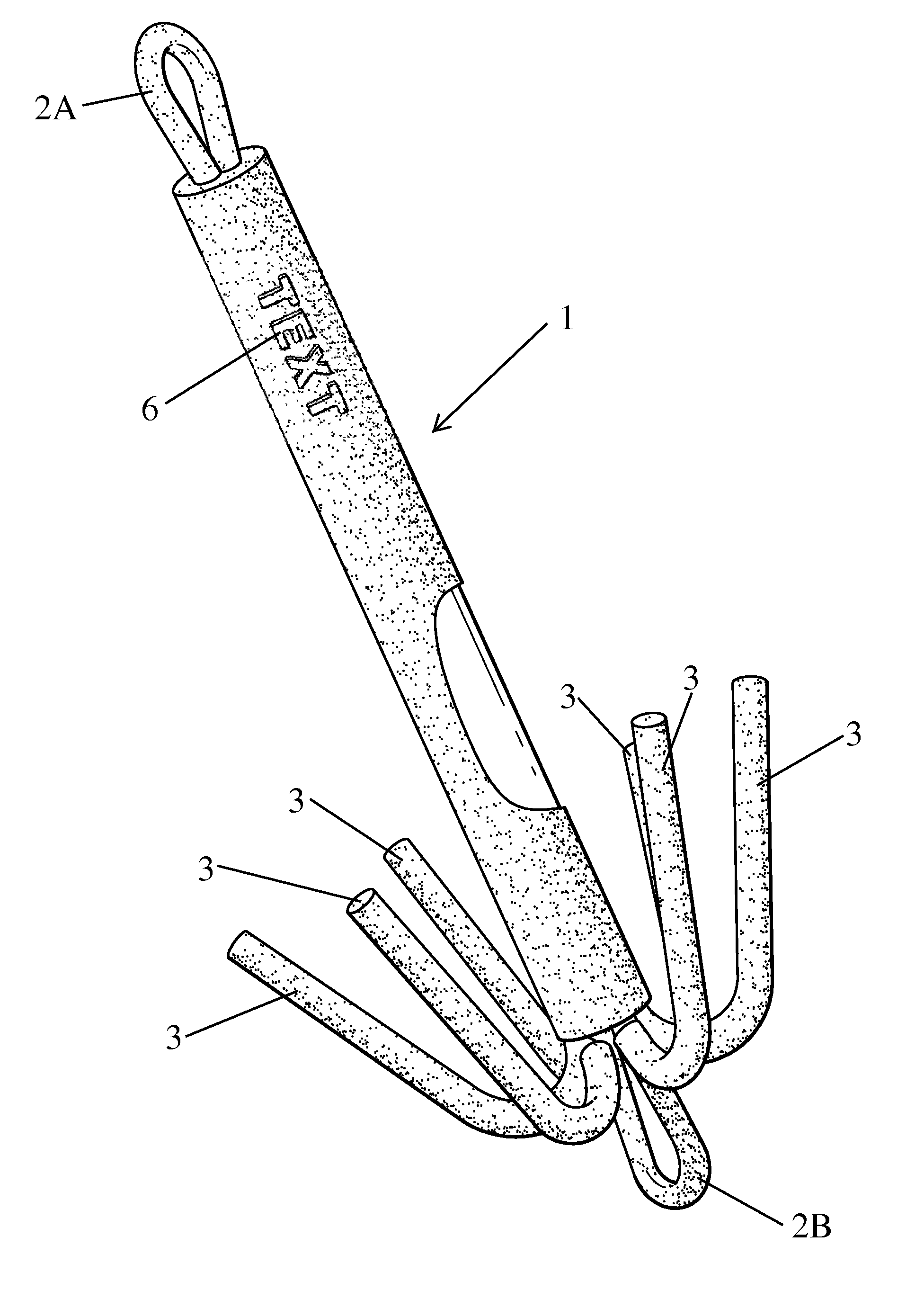
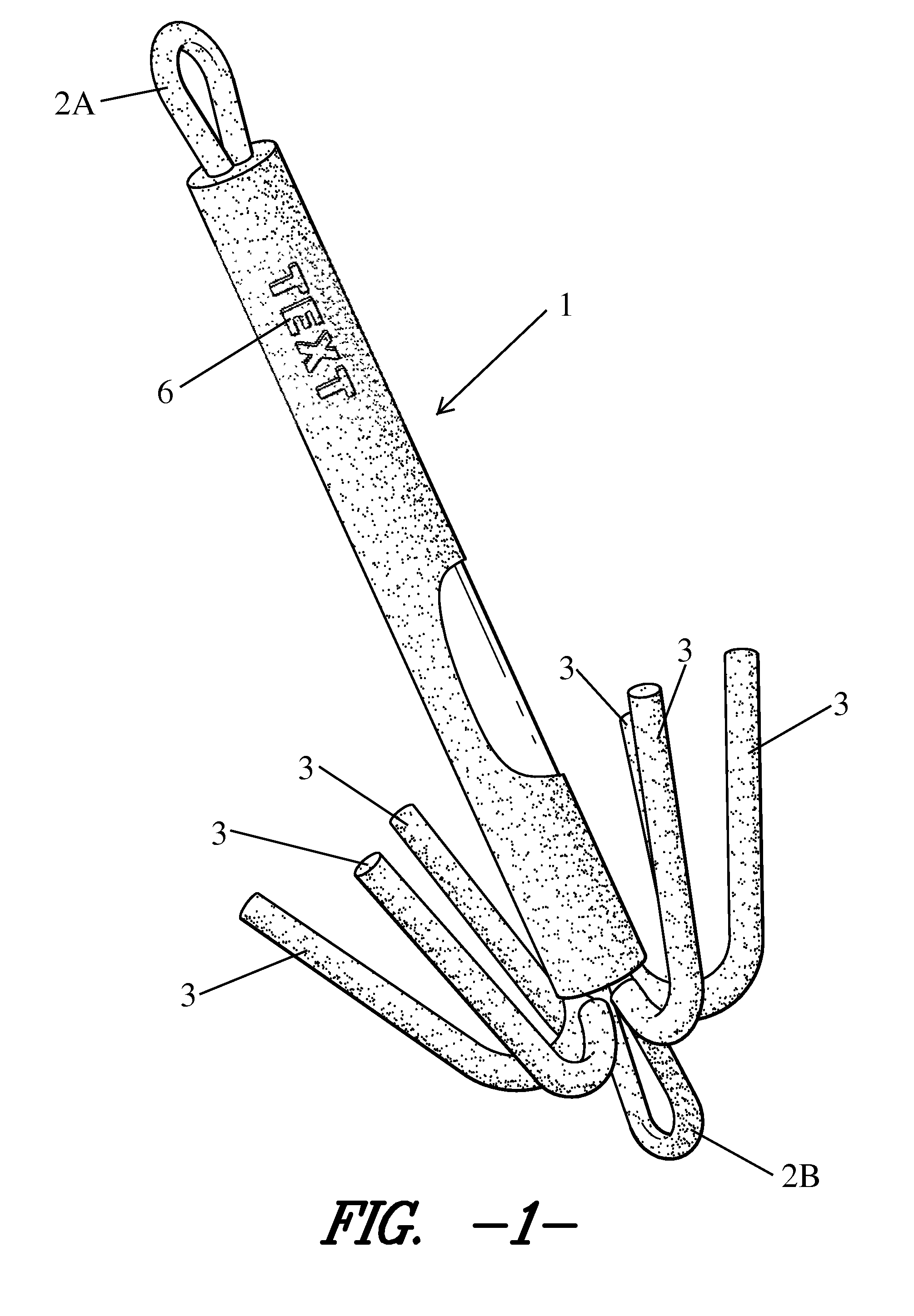
[0015]As seen in FIGS. 1-4, The disclosed anchor includes a main body 1 which is formed of a cylindrical surface enclosed by circular faces on each end. A rode attachment point 2A, 2B is provided on one or both ends of the main body 1, on or near one or both endpoints of the longitudinal axis of the main body 1 (i.e., on or near the centerpoint of one or both of the circular end faces). The attachment points 2A, 2B may be provided, e.g., as eye bolts threadedly received by each circular face of the main body, or, as shown in the attached drawings, in the form of a semi-circular arch. The disclosed anchor further includes a plurality of flexible tines 3 attached to one end of the cylindrical surface of the main body 1, the end of the main body 1 where the tines 3 are attached is referred to as the bottom end.

[0016]A rode attachment point 2A is provided on or near the top endpoint of the longitudinal axis of the main body 1. A second rode attachment point 2B may optionally be provided...


PUM

PropertyMeasurementUnit
angleaaaaaaaaaa
flexibleaaaaaaaaaa
metallicaaaaaaaaaa

Abstract

A lightweight anchor for small boats and a method of making the same. The anchor includes a protective coating. The anchor also includes a release mechanism. The primary release mechanism is provided by flexible tines. The flexible tines make the anchor adaptable to work in various conditions, such as rocky bottoms, reefs, or other similar conditions. The flexible tines also make the anchor easily retrievable. If the tines are bent during retrieval, the tines may be readily returned to their operative configuration.

Description

BACKGROUND OF THE INVENTION[0001]1. Field of the Invention[0002]The present invention relates to an anchor for small boats which is particularly adapted to be useful for anchoring in a variety of conditions, including rocky bottoms and reefs, and a method of making such an anchor which provides enhanced durability, strength and a longer usable life.[0003]2. Description of Related Art[0004]Known boat anchors generally rely primarily on their weight to serve their intended function. Heavyweight anchors have disadvantages including that they are difficult to retrieve because, among other things, their significant weight requires considerable effort to haul up by hand. Additionally, heavyweight anchors function best in sandy bottoms, but are poorly adapted to rigid bottoms, such as rocky bottoms. A heavyweight anchor is designed to displace sand from the bottom of the body of water in which the boat is to be anchored, as the heavyweight anchor sinks into the sand, displaced sand settles...

Claims


Application Information

Patent Timeline
Patent Type & Authority Applications(United States)
IPC IPC(8): B63B21/24B05D5/00B05D1/02
CPCB63B21/24B05D5/00B05D1/02B63B21/26
Inventor SAMUELS, GEOFF
Owner SAMUELS GEOFF
Why Eureka
Try Eureka