Sheet stacking apparatus, sheet feeding apparatus, and image forming apparatus

Active Publication Date: 2015-07-09
CANON KK
View PDF3 Cites 1 Cited by
  • Summary
  • Abstract
  • Description
  • Claims
  • Application Information

AI Technical Summary

Benefits of technology

The patent describes a device for stacking sheets of material. The device includes a base, a portion for stacking sheets, and a mechanism that allows the sheets to swing up and down about a central point. The device also has a mechanism that helps reduce the angle at which the sheets swing.

Problems solved by technology

Therefore, there is a problem that the envelope cannot be fed reliably.

Method used


Image

  • Sheet stacking apparatus, sheet feeding apparatus, and image forming apparatus
  • Sheet stacking apparatus, sheet feeding apparatus, and image forming apparatus
  • Sheet stacking apparatus, sheet feeding apparatus, and image forming apparatus

Examples


Embodiment Construction

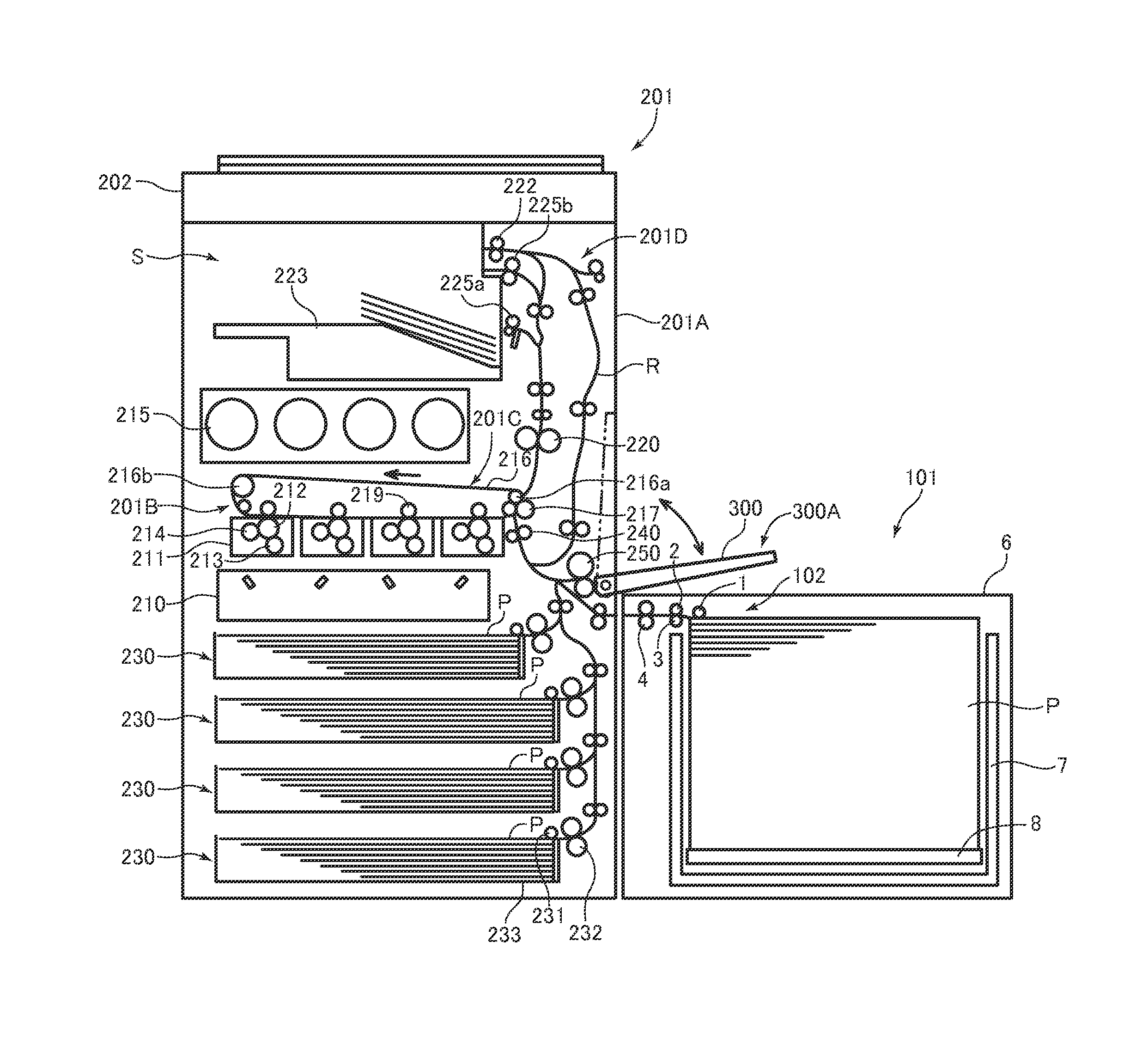
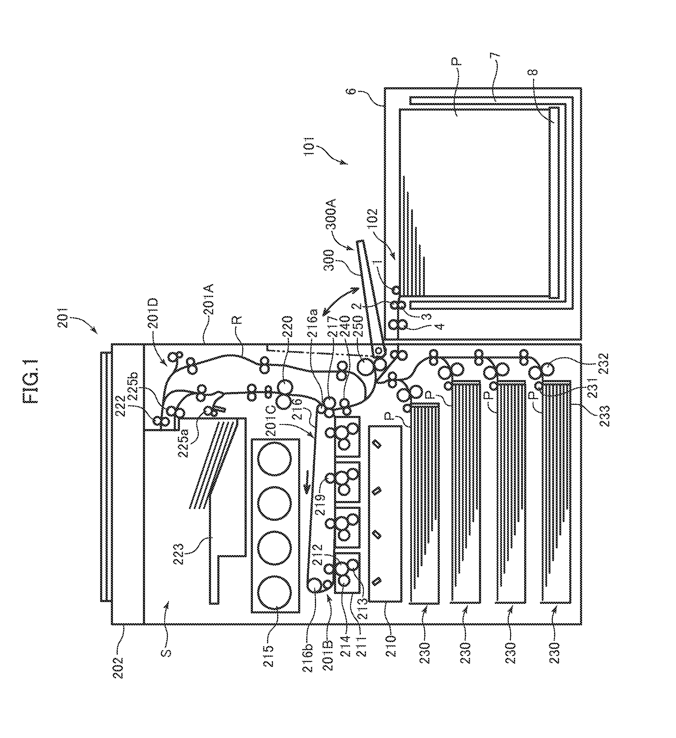
[0033]Hereinafter, a mode for carrying out this disclosure will be described in detail with reference to the drawings. FIG. 1 is a drawing illustrating a general configuration of a full-color laser beam printer that is an example of an image forming apparatus including a sheet feeding apparatus according to an embodiment of this disclosure.

[0034]In FIG. 1, reference numeral 201 denotes a full-color laser beam printer (hereinafter, referred to as a printer), reference numeral 201A denotes a printer body as an image forming apparatus body, reference numeral 201B denotes an image forming portion configured to form an image on a sheet, and reference numeral 220 denotes a fixing unit. Reference numeral 202 denotes an image reading unit as an upper apparatus installed above the printer body 201A substantially horizontally, and a discharge space S for discharging a sheet is formed between the image reading unit 202 and the printer body 201A.

[0035]Reference numeral 230 denotes a sheet feedi...


PUM


Abstract

A sheet stacking apparatus includes a base member, a sheet stacking portion on which sheets are stacked, and a biasing portion configured to bias the sheet stacking portion.The sheet stacking portion is swingably supported by the base member, and the biasing portion biases the sheet stacking portion such that a swing angle is reduced.

Description

BACKGROUND OF THE INVENTION[0001]1. Field of the Invention[0002]This disclosure relates to a sheet stacking apparatus, a sheet feeding apparatus, and an image forming apparatus.[0003]2. Description of the Related Art[0004]Nowadays, in image forming apparatus such as copying machines, printers, and facsimiles, those configured to form images on a sheet fed from a sheet feeding apparatus by an image forming portion is widely used. The sheet feeding apparatus is generally configured to demountably mount a sheet feeding cassette as a sheet storage portion configured to store sheets in an apparatus main body, and feed the sheets stored in the sheet feeding cassette by a pickup roller provided on the apparatus main body automatically.[0005]Examples of the sheet feeding apparatus of this type include those including a tray configured to be moved upward and downward by an elevating unit so as to feed the sheets stacked on the tray of the sheet feeding cassette by pressing with a pickup roll...

Claims


Application Information

Patent Timeline
IPC IPC(8): B65H1/08B65H1/14B65H1/04
CPCB65H1/08B65H1/14B65H1/04B65H2402/31B65H2405/1116B65H2405/15B65H2701/11252B65H2701/1916B65H1/12B65H2405/11151B65H2402/20
Inventor NAKAGAWA, TOMOHITOKUSHIDA, HIDEKI
Owner CANON KK
Why Eureka
Try Eureka