Scale, measuring apparatus, image formation apparatus, scale fabricating unit, and scale fabrication method

a technology of scale and scale, applied in the direction of manufacturing tools, instruments, material analysis, etc., can solve the problems of displacement or velocity of rotating objects that cannot be provided with drive control at high accuracy, displacement or velocity of rotating objects that cannot be correctly detected at the joint portion of scale, etc., to reduce the influence of the joint portion and high accuracy of detecting displacement or velocity of rotating objects

Inactive Publication Date: 2015-07-09
CANON KK
View PDF29 Cites 1 Cited by
  • Summary
  • Abstract
  • Description
  • Claims
  • Application Information

AI Technical Summary

Benefits of technology

[0007]The present invention provides a scale, a measuring apparatus, an image formation apparatus, a scale fabricating unit, and a scale fabrication method that can highly accurately detect a displacement or velocity of a rotating object by reducing influence of a joint portion.

Problems solved by technology

However, the formation of the scale on the surface of the rotating object involves matching, to an desired interval, an interval between a mark formed first and a mark formed last on the surface of the rotating object at a joint portion therebetween, which causes difficulties.
Since the periodicity of marks is lost at such a joint portion of the scale, the displacement or velocity of the rotating object cannot be correctly detected, and the rotating object cannot be provided with a drive control at high accuracy.
Thus, with the configuration disclosed in Japanese Patent Laid-open No. 2005-345359, the displacement or velocity of the rotating object cannot be correctly detected at the joint portion of the scale, and the rotating object cannot be provided with a drive control at high accuracy.

Method used


Image

  • Scale, measuring apparatus, image formation apparatus, scale fabricating unit, and scale fabrication method
  • Scale, measuring apparatus, image formation apparatus, scale fabricating unit, and scale fabrication method
  • Scale, measuring apparatus, image formation apparatus, scale fabricating unit, and scale fabrication method

Examples


embodiment 1

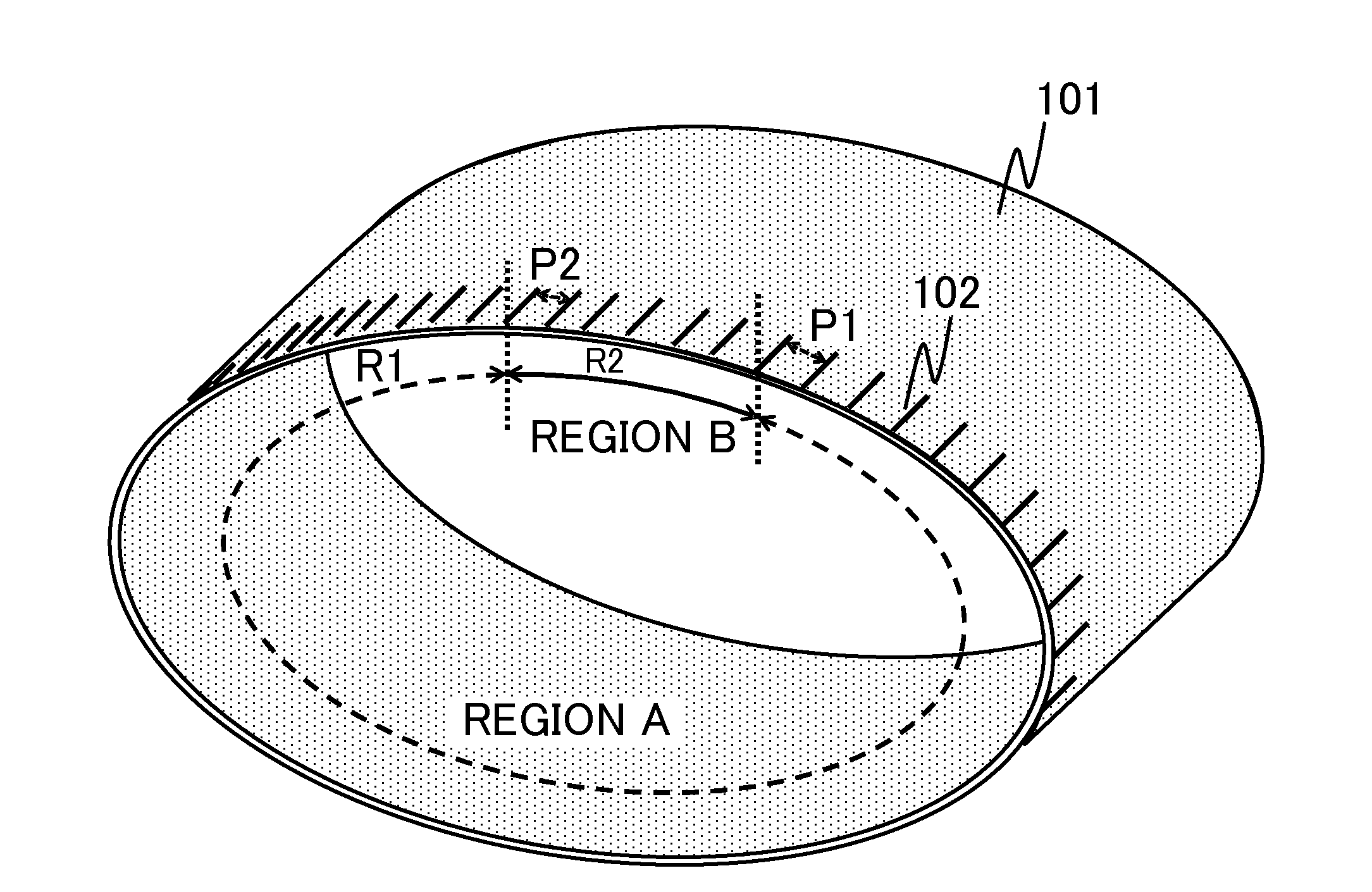
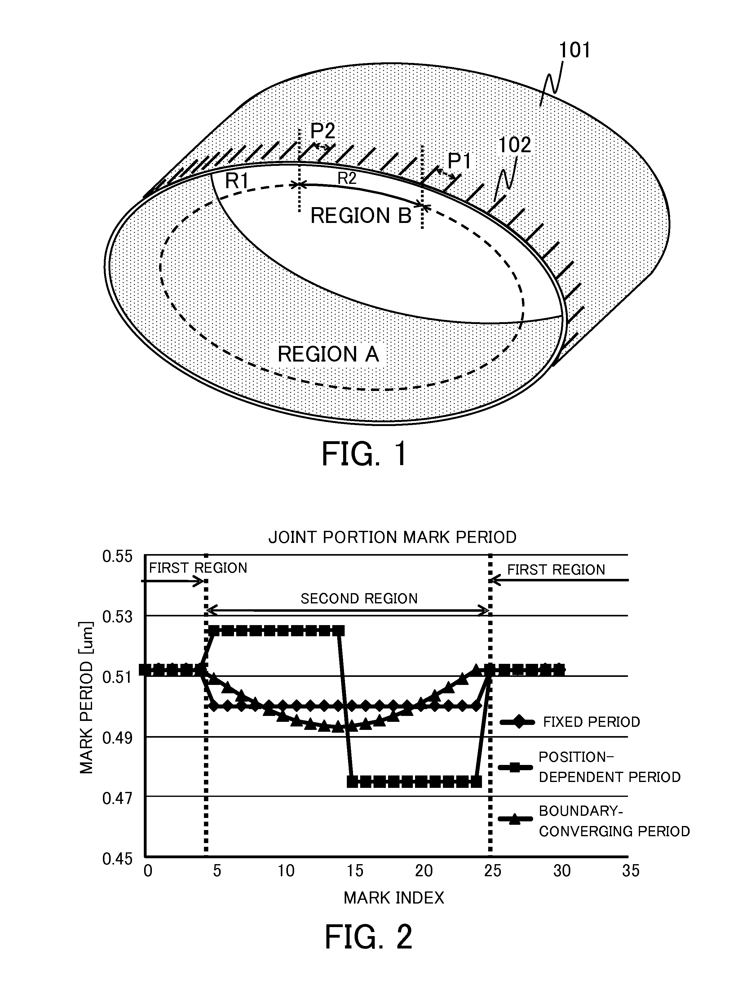
[0029]First, referring to FIG. 1, a scale in Embodiment 1 of the present invention will be described. FIG. 1 is a configuration diagram of a seamless scale 102 (the scale) in the present embodiment.

[0030]The seamless scale 102 is formed on a surface of a rotating object 101, which has a total length of R (=R1+R2), and is used to measure a displacement or velocity of the rotating object 101. The seamless scale 102 is provided with a plurality of marks formed in a predetermined period on the surface of the rotating object 101. The seamless scale 102 includes a region A (first region) having a length R1 and a region B (second region) having a length R2. The region A is a region in which a first mark row including a plurality of marks arranged in a first period P1 is formed. The region B is a region in which a second mark row including a plurality of marks arranged in a second period P2 is formed. Thus, the seamless scale 102 is a scale in which a periodic mark row including the first m...

embodiment 2

[0063]Next, a fabricating unit (manufacturing unit) and a method of fabricating (manufacturing) the seamless scale 102 in Embodiment 2 of the present invention will be described.

[0064]FIG. 8 is a configuration diagram of a fabricating unit 800 for the seamless scale. In FIG. 8, a mark formation control unit 804 (control unit) calculates information of the displacement of the surface of the rotating object 101 (rotating object surface displacement information) at a mark formation position based on rotational amount information (rotational amount information of the rotating object 101) from a rotating object driver 802 (drive unit). The mark formation control unit 804 outputs, in accordance with the displacement of the surface of the rotating object 101, a mark formation command to a mark formation unit 805 to form a periodic mark row in the first period P1 in the first region on the surface of the rotating object 101.

[0065]A leading mark detection unit 806 (detection unit) detects a ...

embodiment 3

[0077]Next, a fabricating unit (manufacturing unit) and a method of fabricating (manufacturing) the seamless scale 102 in Embodiment 3 of the present invention will be described.

[0078]FIG. 11 is a configuration diagram of a fabricating unit 1100 for the seamless scale and schematically illustrates the fabricating unit that fabricates the seamless scale 102 on the surface of the rotating object 101. As illustrated in FIG. 11, the rotating object 101 is rotated through a drive roller 1102 by a driving motor 1103. A white arrow in FIG. 11 represents a conveying direction of the rotating object 101. The drive roller 1102 is provided with a rotary encoder 1106. A mark-forming control apparatus 1104 (mark formation control unit) calculates, based on rotational amount information obtained from the rotary encoder 1106 and a diameter of the drive roller 1102 (collectively referred to as drive roller rotation information), information of the displacement of the surface of the rotating object ...


PUM

PropertyMeasurementUnit
length R2aaaaaaaaaa
length R2aaaaaaaaaa
velocityaaaaaaaaaa

Abstract

A scale is configured to measure a displacement or velocity of a rotating object. The scale includes a first region that includes a first mark row including a plurality of marks arranged in a first period, and a second region that includes a second mark row including a plurality of marks arranged in a second period having a phase continuity with the first mark row formed in the first region. A periodic mark row including the first mark row and the second mark row is formed over an entire circumference of the rotating object including the first region and the second region.

Description

BACKGROUND OF THE INVENTION[0001]1. Field of the Invention[0002]The present invention relates to a scale formed on a surface of a rotating object and used to detect a displacement or velocity.[0003]2. Description of the Related Art[0004]In a conventional method of detecting a displacement or velocity of a rotating object, a scale formed on a surface of the rotating object is used. Methods of forming the scale on the surface of the rotating object include a method of directly forming the scale on the surface of the rotating object using a laser marker. However, the formation of the scale on the surface of the rotating object involves matching, to an desired interval, an interval between a mark formed first and a mark formed last on the surface of the rotating object at a joint portion therebetween, which causes difficulties. Since the periodicity of marks is lost at such a joint portion of the scale, the displacement or velocity of the rotating object cannot be correctly detected, an...

Claims


Application Information

Patent Timeline
Patent Type & Authority Applications(United States)
IPC IPC(8): G01D5/347B23K26/08B23K26/36
CPCG01D5/34707B23K26/0823B23K26/365
Inventor FUKUHARA, TAKASHI
Owner CANON KK
Why Eureka
Try Eureka