Devices for use with computers

a technology for computers and devices, applied in instruments, electric digital data processing, cathode-ray tube indicators, etc., can solve the problems of frustrating users, difficult for users to benefit from intuitive touch-screen controls while using keyboard and mouse, and inefficient touch-screen keyboards

Inactive Publication Date: 2015-07-09
SWIFTPOINT LTD
View PDF2 Cites 27 Cited by
  • Summary
  • Abstract
  • Description
  • Claims
  • Application Information

AI Technical Summary

Benefits of technology

[0080]The inclination is effected by a rotation of the base contact plane about a reorientation axis which may include components in both the X and Y dimensions with a majority of rotation occurring about a Y axis. It will be appreciated that the most comfortable rotation for a user holding the pointing device will be a left of the device a rolling of the wrist and a slight backwards tilt. This would result in mainly clockwise rotation for a right handed user and anticlockwise rotation for a left-handed user with backward tilt in both cases. The mouse may also be lifted to assist in the reorientation.
[0195]The aforementioned device thus avoids the need for special driver software or user interface as the vast majority of computers are already configured to operate with a keyboard and are capable of receiving standardised keyboard signal codes.

Problems solved by technology

However, touch-screen keyboards are not as efficient as a keyboard for entering large volumes of text and so many users may use a separate keyboard to enter data on a touch-screen controlled computer to assist in data entry.
Moreover, if frequent manipulation of the touch-screen is required the user's fingers will frequently occlude on-screen items which may frustrate the user.
However, touch-screen operating systems are primarily designed for touch-input and thus many touch controls are not as easily performed by a mouse or keyboard combination, making it difficult for users to benefit from the intuitive touch-screen controls while using keyboard and mouse.
This method is unintuitive for many people and strains a user's hand as they must grip the mouse to move it while placing pressure on a button.
However, the use of unique drivers for devices can be a burden for users as they must install the software before they can configure and / or use their device.
However, most devices have no display screen and so it can be difficult for a user to determine how to configure the device and what changes they have made to the device.

Method used


Image

  • Devices for use with computers
  • Devices for use with computers
  • Devices for use with computers

Examples


first embodiment

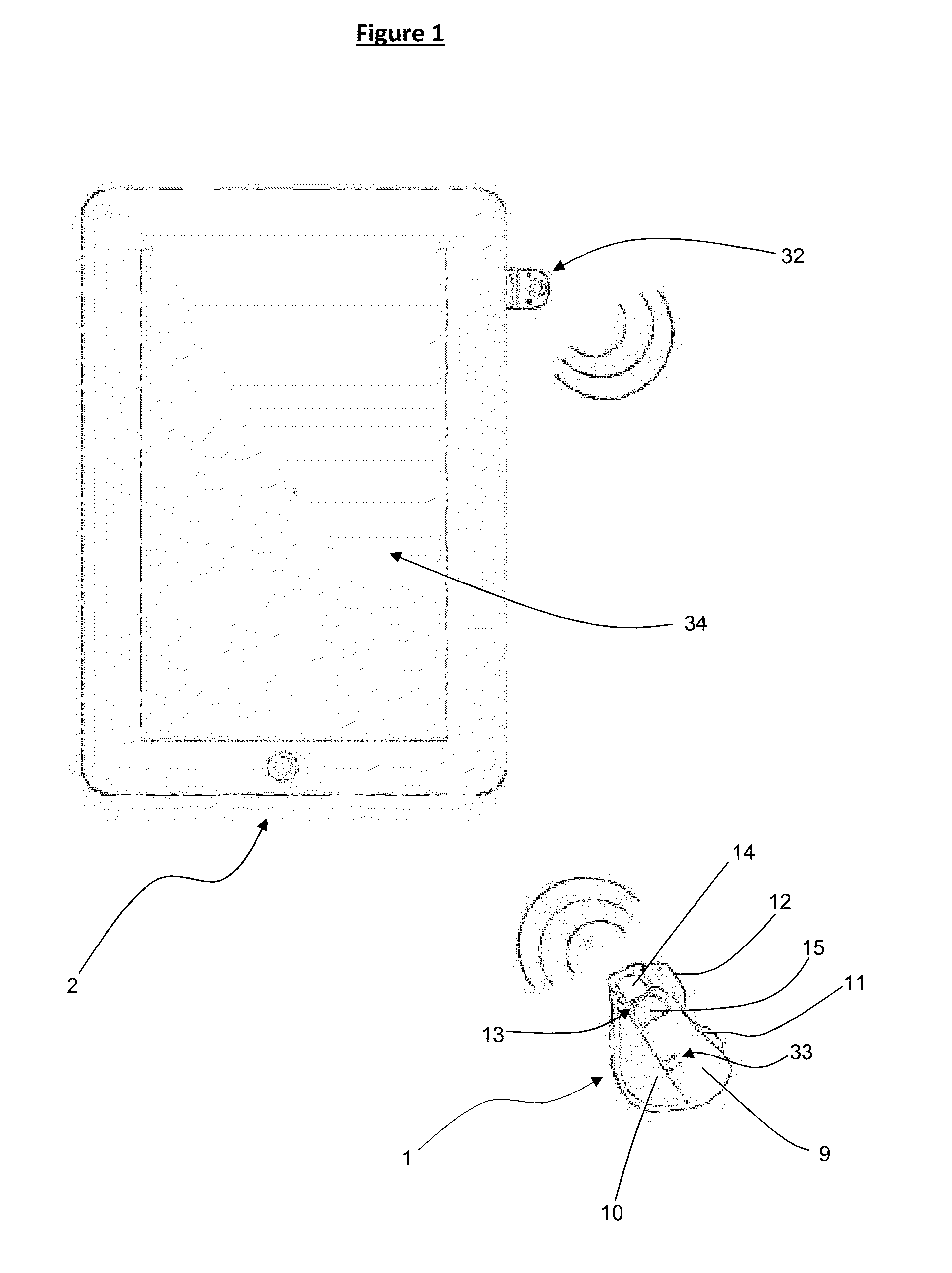
[0278]FIGS. 12-14 show another mouse according to a preferred embodiment of the present invention. This mouse (100) is much larger (approximately 12 cm by 6 cm by 4 cm) than the first embodiment and has a more conventional palm-grip type upper body (102).

[0279]The mouse (100) also has a scroll wheel (105) and two contact sensors provided in the form of left (103) and right (104) mouse buttons. Supporting feet (108) form a base contact plane (107) and are used to support the mouse as it slides over a work surface.

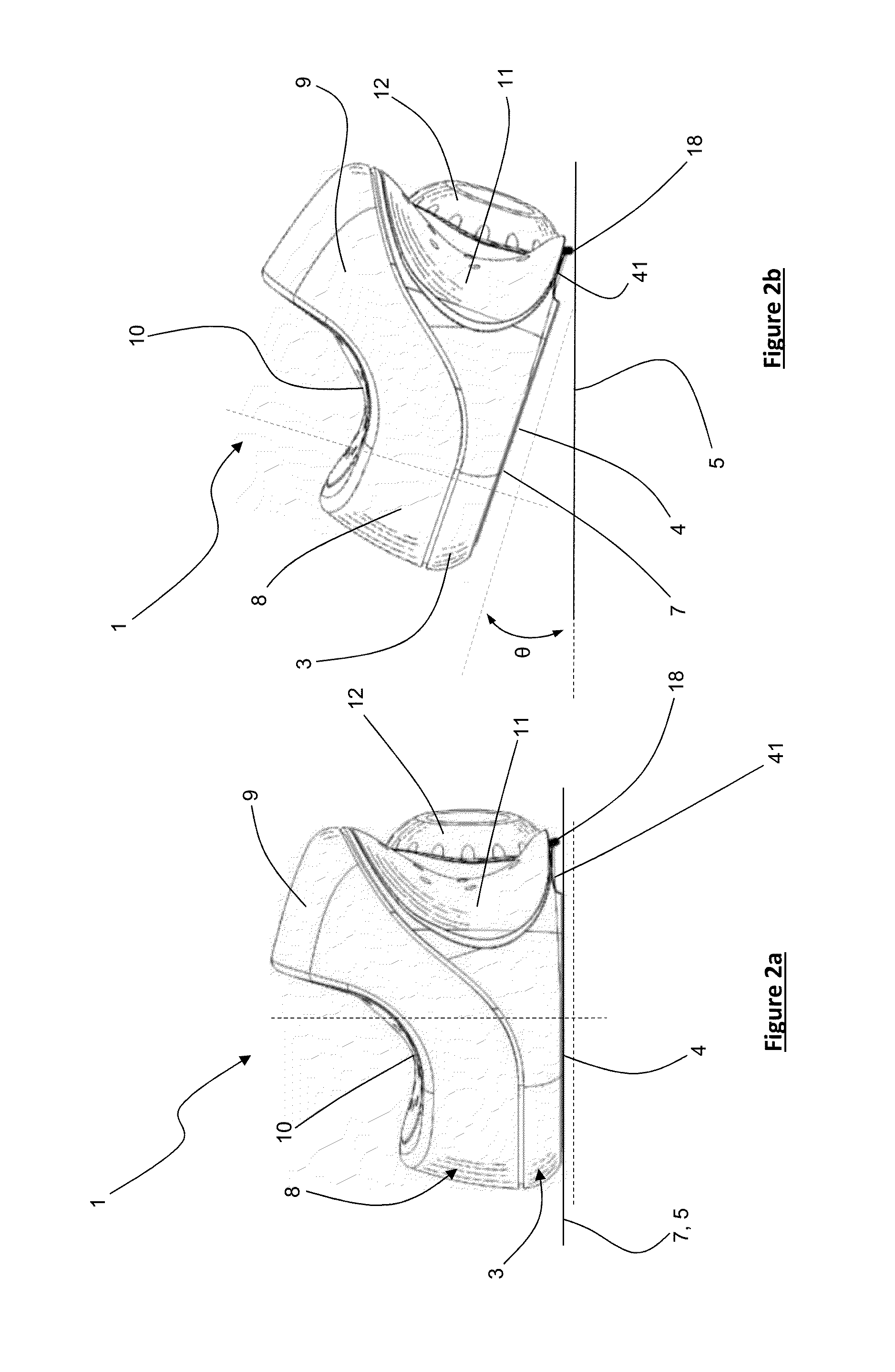
[0280]The mouse (100) has a mode sensor (109) positioned to protrude downward from the base (101). An optical movement detection system (110) is provided and configured to provide a focal zone at or very close to the mode sensor (109). The optical system (110) has a similar arrangement to the first mouse embodiment (1) as shown in FIG. 9 and is capable of detecting mouse movement in both first (FIG. 13) and second (FIG. 14) orientations.

[0281]The base (101) has a right side ...

third embodiment

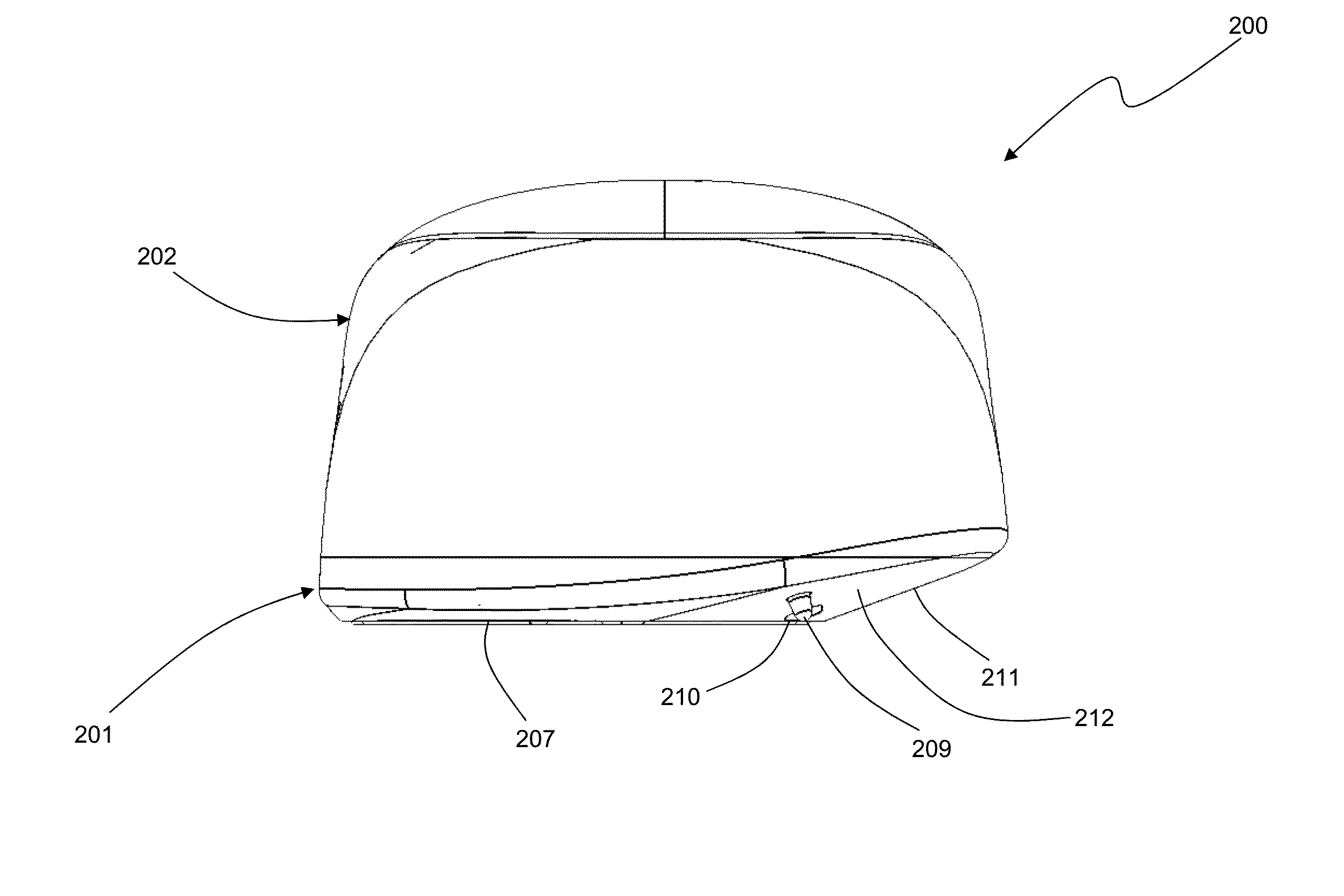
[0282]A mouse (200) is shown in FIGS. 15 and 16 and has the same components and general shape as the mouse of FIGS. 12-14, i.e. the mouse (200) has a scroll wheel (205) left (203) and right (204) mouse buttons, supporting feet (208) forming a base contact plane (207) and an inclined right side portion (111)

[0283]The mouse (200) differs to mouse (100) in that the mode sensor (209) is located toward the rear of the mouse (200) and the mouse has an inclined rearward chamfer (212) to allow the user to tile the mouse backwards and to the right, rather than forwards and to the right as in the previous embodiment (100).

[0284]The mice (100, 200) provide a more conventional ‘desktop’ palm-grip shape but provide the same functionality as the smaller mouse (1) through use of two different operating modes, the second mode activated by reorientating the mouse to activate the mode sensor (109, 209).

[0285]A touch-based input operating system typically has no need for an on-screen pointer as the u...


PUM


Abstract

A computer mouse for use with a computer, including: a base with a lower surface configured for sliding across a work surface and having at least one portion forming part of a base contact plane; an upper body extending from the base; a contact sensor; an optical movement sensor system capable of detecting mouse movement relative to the work surface, a communication system, for communicating computer-readable movement and / or position data signals from the device to a computer, wherein the mouse is configured to operate in a first mode when orientated in a first orientation, and a second mode when orientated in a second orientation when the base contact plane is inclined with respect to the first orientation, and wherein the optical movement sensor system is configured to capture an image of the work surface in both the first and second modes to determine device movement in both modes.

Description

CROSS-REFERENCE TO OTHER APPLICATIONS[0001]This is a continuation-in-part of International Patent Application No: PCT / IB2013 / 055772, filed on Jul. 12, 2013, which claims priority from New Zealand Patent Application No. 601229, filed on Jul. 12, 2012 and New Zealand Patent Application No. 610609, filed May 14, 2013; and is a continuation-in-part of U.S. patent application Ser. No. 13,685,653 filed on Nov. 26, 2012, which is a continuation of U.S. patent application Ser. No. 11 / 815,094, filed on Dec. 2, 2008, which is a National Phase of International Application No. PCT / NZ2006 / 000007, filed on Jan. 30, 2006, which claims priority from New Zealand Patent Application No. 535766, filed on Jan. 30, 2005, all of which are incorporated herein by reference in their entirety.TECHNICAL FIELD[0002]The present invention relates generally to improvements in devices for use with computers. In particular the present invention relates generally to an improved computer mouse, a configurable device f...

Claims


Application Information

Patent Timeline
Patent Type & Authority Applications(United States)
IPC IPC(8): G06F3/0354
CPCG06F3/03543G06F3/017G06F3/0317G06F3/038G06F3/0482G06F3/0483G06F2203/0333G06F2203/0335G06F2203/0384
Inventor ODGERS, GRANT NEVILLEEARLY, WILLIAMTHIRD, SIMONBEACH, DAVID
Owner SWIFTPOINT LTD
Why Eureka
Try Eureka