
Calibration of multiple rigid bodies in a virtual reality system

a virtual reality system and rigid body technology, applied in the field of calibration systems, can solve the problems of affecting the accuracy of virtual reality systems,

Active Publication Date: 2015-07-09
META PLATFORMS TECH LLC
View PDF2 Cites 110 Cited by
  • Summary
  • Abstract
  • Description
  • Claims
  • Application Information

AI Technical Summary

Benefits of technology

The patent describes a virtual reality (VR) headset that can track the position of a user's head and the movement of their hands and body. The headset includes a front and rear rigid body that are non-rigidly coupled together, so the system needs to recalibrate when the front and rear rigid bodies move relative to each other. The VR system uses slow calibration data and fast calibration data to determine the position of the front and rear rigid bodies. The VR system can adjust the position of the front and rear rigid bodies to match the predicted positions, and the user's head and hands can be tracked accurately during the calibration process.

Problems solved by technology

Operating improperly calibrated VR device may result in improper tracking of the position or motion of the headset, which causes a dissonance between user motion and media presented to the user via the headset.
Moreover, one or more of the components determining headset position and movement can lose calibration over time or with use.
For example, changes in temperature or vibration may cause a camera imaging the motion of the headset to lose calibration.

Method used


Image

  • Calibration of multiple rigid bodies in a virtual reality system
  • Calibration of multiple rigid bodies in a virtual reality system
  • Calibration of multiple rigid bodies in a virtual reality system

Examples


Embodiment Construction

System Architecture

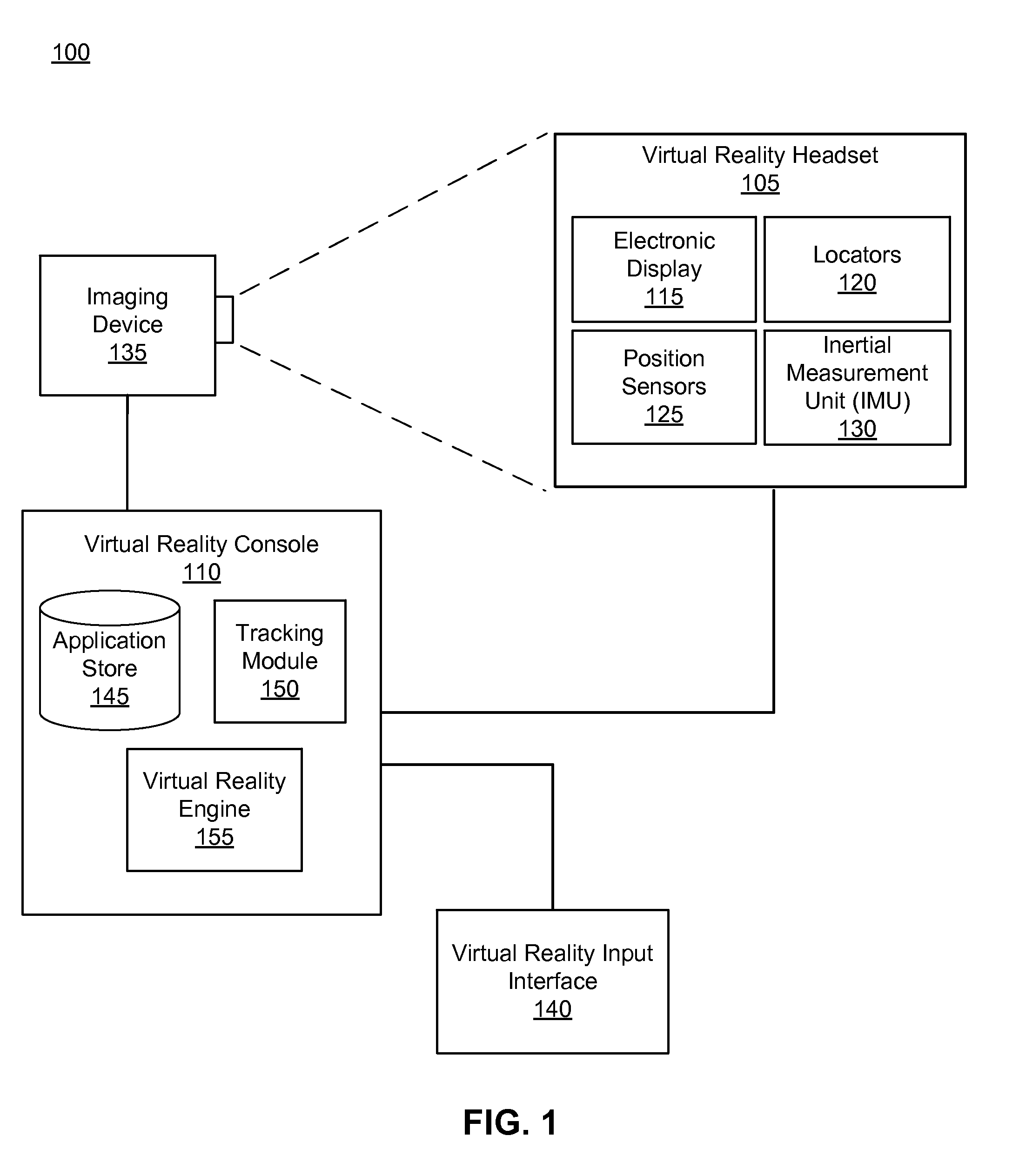
[0020]FIG. 1 is a block diagram of one embodiment of a virtual reality (VR) system environment 100 in which a VR console 110 operates. The system environment 100 shown by FIG. 1 comprises a VR headset 105, an imaging device 135, and a VR input interface 140 that are each coupled to the VR console 110. While FIG. 1 shows an example system 100 including one VR headset 105, one imaging device 135, and one VR input interface 140, in other embodiments any number of these components may be included in the system 100. For example, there may be multiple VR headsets 105 each having an associated VR input interface 140 and being monitored by one or more imaging devices 135, with each VR headset 105, VR input interface 140, and imaging devices 135 communicating with the VR console 110. In alternative configurations, different and / or additional components may be included in the system environment 100.

[0021]The VR headset 105 is a head-mounted display that presents media to a ...


PUM


Abstract

A virtual reality (VR) console receives slow calibration data from an imaging device and fast calibration data from an inertial measurement unit on a VR headset including a front and a rear rigid body. The slow calibration data includes an image where only the locators on the rear rigid body are visible. An observed position is determined from the slow calibration data and a predicted position is determined from the fast calibration data. If a difference between the observed position and the predicted position is greater than a threshold value, the predicted position is adjusted by a temporary offset until the difference is less than the threshold value. The temporary offset is removed by re-calibrating the rear rigid body to the front rigid body once locators on both the front and rear rigid body are visible in an image in the slow calibration data.

Description

CROSS-REFERENCE TO RELATED APPLICATIONS[0001]This application claims the benefit of U.S. Application No. 62 / 088,088, filed Dec. 5, 2014, U.S. Provisional Application No. 62 / 088,085, filed Dec. 5, 2014, and U.S. Provisional Application No. 61 / 923,895, filed on Jan. 6, 2014, all of which are incorporated by reference in their entirety.BACKGROUND[0002]The present disclosure generally relates to calibration systems, and more specifically relates to calibrating virtual reality systems.[0003]Virtual reality (VR) devices include components for determining position and movement of a headset worn by a user. These components need to be calibrated at various times, initially due to manufacturing tolerances and subsequently due to normal use of the system. Operating improperly calibrated VR device may result in improper tracking of the position or motion of the headset, which causes a dissonance between user motion and media presented to the user via the headset. Moreover, one or more of the co...

Claims


Application Information

Patent Timeline
IPC IPC(8): G06T11/00G02B27/01
CPCG06T11/00G02B2027/0187G02B27/017G02B2027/0178G02B2027/0138G02B2027/014G06T2207/30204G06T7/75G06F1/163G06F3/011G06F3/012G06T7/80G06F1/00G06T15/205G06T19/006G06F3/0346H04N17/04G06T7/74G06T2207/10016
Inventor KATZ, DOVSHINE, JONATHANMILLER, ROBIN MICHAEL
Owner META PLATFORMS TECH LLC
Learn More