Conveying device and printing apparatus
a technology of conveying device and printing apparatus, which is applied in the direction of office printing, thin material handling, printing, etc., can solve the problem of increasing the damage to the sheet,
- Summary
- Abstract
- Description
- Claims
- Application Information
AI Technical Summary
Benefits of technology
Problems solved by technology
Method used
Image

Examples
first embodiment
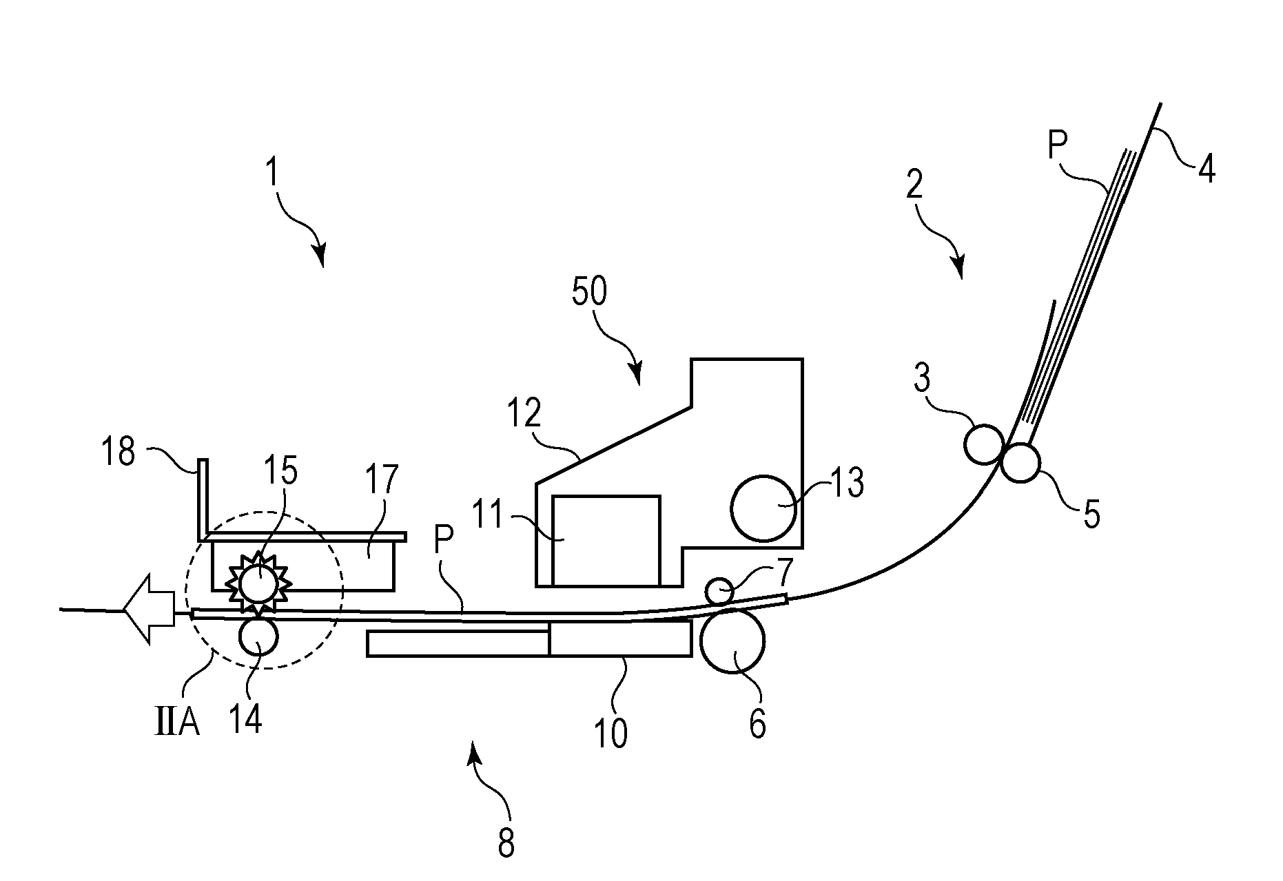
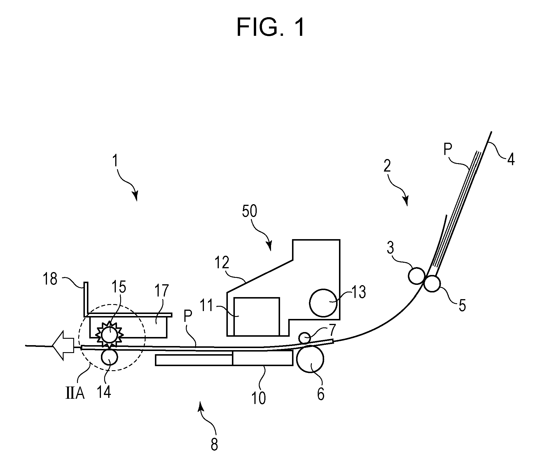
[0021]FIG. 1 is a general view of a printing apparatus 1 according to a first embodiment. The printing apparatus 1 includes a sheet feeding section 2 that feeds a sheet from a stack of sheets, a sheet conveying section 8 that conveys the sheet to a position below a printing section 50, and the printing section 50 that ejects ink toward the surface of the sheet. A side of the printing apparatus 1 on which the sheet feeding section 2 is provided is defined as the upstream side in the direction of sheet conveyance, and a side of the printing apparatus 1 on which the sheet conveying section 8 is provided is defined as the downstream side in the direction of sheet conveyance.
[0022]The sheet feeding section 2 includes a tray 4 on which a plurality of sheets P are stacked, a feed roller 3 that feeds one of the stack of sheets P toward the sheet conveying section 8, and a separating roller 5 that faces the feed roller 3 and is made of a highly frictional member. When the feed roller 3 is ro...
second embodiment
[0049]FIG. 7 is a detailed view illustrating a spur unit 150 and associated elements according to a second embodiment. The second embodiment differs from the first embodiment in that one spur holder supports a plurality of spurs by using one common shaft.
[0050]In the spur unit 150, one spur holder 17 supports spurs 150a and 150b by using a common shaft 19. Edges 150d of teeth of the spurs 150a and 150b are provided on the side A with respect to the centers of the spurs 150a and 150b, as in the first embodiment. The spur unit 150 may include three or more spurs that are supported by one shaft.
[0051]To convey the sheet P with high accuracy, a predetermined pressing force needs to be applied from the spur to the sheet P. If the pressing force from the spur is too large, a noticeable spur mark may be formed in the sheet P. Hence, the spurs 150a and 150b are provided on one shaft 19 so that the area of contact between the sheet P and the edges 150d is increased, whereby a desirable press...
third embodiment
[0054]FIG. 8 is a detailed view illustrating spur units and associated elements according to a third embodiment that are seen from the downstream side in the direction of sheet conveyance. In the third embodiment, a plurality of spur units, each of which corresponds to the spur unit 150 according to the second embodiment, are arranged in a line. The spur units arranged in a line do not all incline toward the same side. The side toward which the spur units incline varies regularly.
[0055]Spur units 150 each have the same configuration as the spur unit 150 according to the second embodiment. That is, the edges 150d are provided on the side A with respect to the center line c-c, and the spur unit 150 is prevented from inclining toward the side A by the projections 30a and 30b. Therefore, the spur unit 150 can easily incline toward the side B.
[0056]Spur units 151 each have teeth 151d provided on the side B with respect to the center line c-c, and is prevented from inclining toward the si...
PUM
 Abstract
Description
Claims
Application Information
 - R&D
- Intellectual Property
- Life Sciences
- Materials
- Tech Scout
- Unparalleled Data Quality
- Higher Quality Content
- 60% Fewer Hallucinations
Browse by: Latest US Patents, China's latest patents, Technical Efficacy Thesaurus, Application Domain, Technology Topic, Popular Technical Reports.
© 2025 PatSnap. All rights reserved.Legal|Privacy policy|Modern Slavery Act Transparency Statement|Sitemap|About US| Contact US: help@patsnap.com