Pin Displacement Assembly

Inactive Publication Date: 2015-07-16
IMAGIK INTL
View PDF0 Cites 0 Cited by
  • Summary
  • Abstract
  • Description
  • Claims
  • Application Information

AI Technical Summary

Benefits of technology

[0024]In yet another aspect, the motion transmission device may include a direct push, linear arm, rather than the arm that is hinged, for displacing the pin contact member. The linear arm does not utilize a hinge, and therefore does not receive a mechanical advantage for the force. The linear arm may be disposed to position directly behind the cavity.
[0025]In one objective of the present invention, the broken pin, separated from the connection plug may be displaced from the cavity without requiring disassembling

Problems solved by technology

In some embodiments, the pin may be separated or broken off from a connection plug, and thereby difficult to access without the connection plug attached.
Those skilled in the art will recognize that that the connection plug is generally fragile, and therefore susceptible to forcibly separating from the pin, especially in a passenger seat of an aviation vehicle w

Method used


Image

  • Pin Displacement Assembly
  • Pin Displacement Assembly
  • Pin Displacement Assembly

Examples


Example

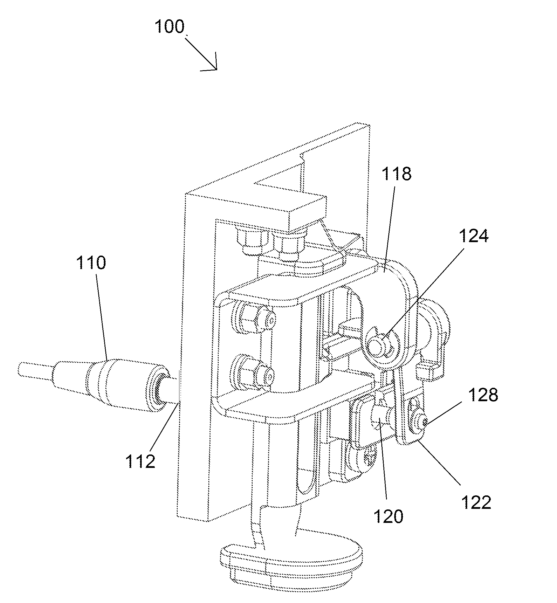
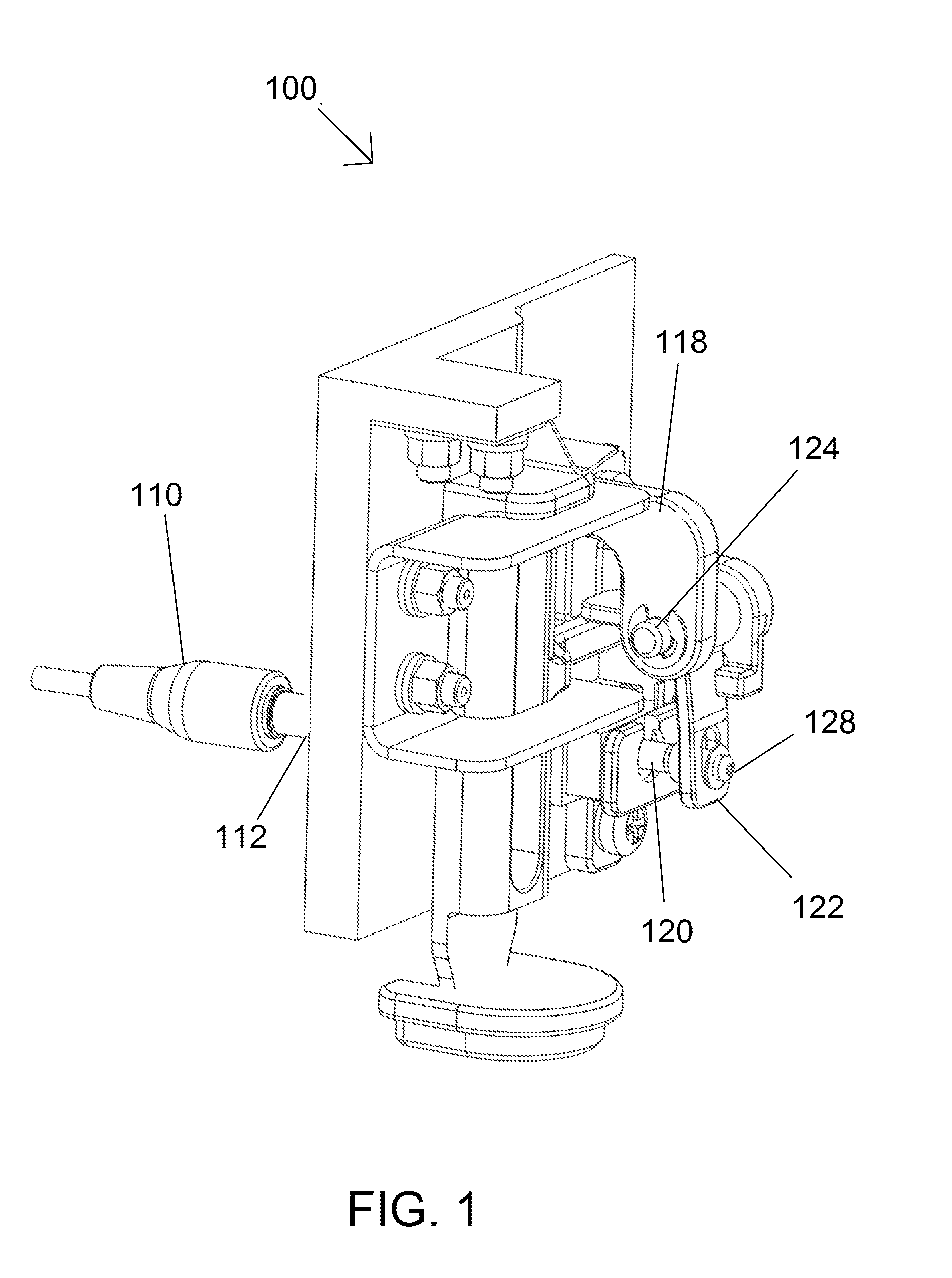
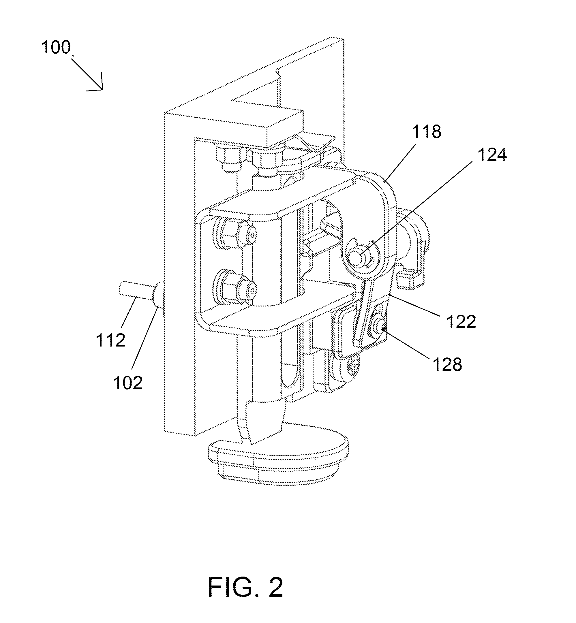
[0037]Like reference numerals refer to like parts throughout the various views of the drawings.

DETAILED DESCRIPTION OF THE INVENTION

[0038]The present invention is best understood by reference to the detailed figures and description set forth herein.

[0039]The following detailed description is merely exemplary in nature and is not intended to limit the described embodiments or the application and uses of the described embodiments. As used herein, the word “exemplary” or “illustrative” means “serving as an example, instance, or illustration.” Any implementation described herein as “exemplary” or “illustrative” is not necessarily to be construed as preferred or advantageous over other implementations. All of the implementations described below are exemplary implementations provided to enable persons skilled in the art to make or use the embodiments of the disclosure and are not intended to limit the scope of the disclosure, which is defined by the claims. For purposes of description her...


PUM

PropertyMeasurementUnit
Lengthaaaaaaaaaa
Forceaaaaaaaaaa
Angleaaaaaaaaaa

Abstract

A pin displacement assembly displaces a pin from a socket. The pin may be broken off from a connection plug and thereby difficult to access from inside a cavity in the socket. The assembly utilizes a lever and fulcrum system to leverage a force used to displace the pin from the cavity. The assembly includes a pin contact member that at least partially positions inside the cavity for facilitated access to the pin. A motion transmission device leverages the force for displacing the pin. The motion transmission device includes an arm. The arm includes an arm lever end and an arm pin end. A hinge positions between the arm lever end and the arm pin end. The hinge alters the direction of the force in the form of torque, by rotating the arm about the hinge. In this manner, the optimal mechanical advantage is realized.

Description

FIELD OF THE INVENTION[0001]The present invention relates generally to pin displacement from a socket. More so, a pin displacement assembly utilizes a mechanical advantage from a lever and fulcrum, and a pin contact member positioned inside the socket to facilitate displacement of the pin from a socket, even if the pin is separated from a connection plug.BACKGROUND OF THE INVENTION[0002]The following background information may present examples of specific aspects of the prior art (e.g., without limitation, approaches, facts, or common wisdom) that, while expected to be helpful to further educate the reader as to additional aspects of the prior art, is not to be construed as limiting the present invention, or any embodiments thereof, to anything stated or implied therein or inferred thereupon.[0003]Typically, a connection plug is a common family of connector typically used for analog signals, primarily audio. It is cylindrical in shape, typically with two, three or four contacts. A p...

Claims


Application Information

Patent Timeline
IPC IPC(8): H01R43/26
CPCH01R43/26H01R24/58H01R43/002H01R2201/26H04R1/1091H04R2420/00Y10T29/49822Y10T29/53283
Inventor VADILLO, PABLO
Owner IMAGIK INTL
Why Eureka
Try Eureka