System and process for forming battery cans

a battery can and process technology, applied in the field of battery cans, can solve the problems of increasing resistance, reducing the operational voltage and the length of time over which the battery can be discharged, and reducing the contact between the can and the cathode, so as to achieve the effect of minimizing the internal resistance of the battery, and facilitating the discharge of the battery can

Inactive Publication Date: 2006-07-20
H & T BATTERY COMPONENTS USA
View PDF9 Cites 24 Cited by
  • Summary
  • Abstract
  • Description
  • Claims
  • Application Information

AI Technical Summary

Benefits of technology

[0015] One advantage of the present invention is that moderate roughnesses of the inner surfaces of the battery cans can be attained. Such roughnesses are desirable in that they minimize the internal resistance of cells into which the cans are incorporated. The minimization of the internal resistance results in superior cell performance.
[0016] Another advantage is that an increased amount of control can be exercised over the manufacturing of the cans. In particular, the walls of the cans can be thinned to a high degree while maintaining close tolerances and uniformity of the sidewall thickness.
[0017] Still another advantage is that the maintenance associated with the tooling is minimized, thereby lowering manufacturing costs (as compared to other methods).

Problems solved by technology

An increase in the resistance of this contact causes a corresponding increase in the internal resistance of the cell, which in turn causes a decrease in the operational voltage and length of time over which the cell can be discharged.
The resistance is oftentimes increased when the interior surfaces of the can exhibit a relatively smooth condition, thereby providing poor contact between the can and cathode and inhibiting the transfer of electrons across the can-to-cathode interface.
Although the methods are similar, there are fundamental differences in the properties of the products produced by these two methods.
However, beyond about a 20% reduction in the thickness of the wall, control of the wall thickness and its uniformity become difficult.
Furthermore, in the drawing and thinning method, tool maintenance needed to maintain sidewall thickness tolerances becomes increasingly difficult as the degree of thinning increases, thereby increasing the costs associated with manufacturing the cans.
However, the drawing and ironing method produces surfaces that are very smooth and less suitable for use in alkaline battery cells.
In the described simple redrawing, the punch will be in intimate contact with the sidewall of the can, resulting in a burnishing or smoothing effect on the inner surface of the sidewall.

Method used


Image

  • System and process for forming battery cans
  • System and process for forming battery cans
  • System and process for forming battery cans

Examples


Embodiment Construction

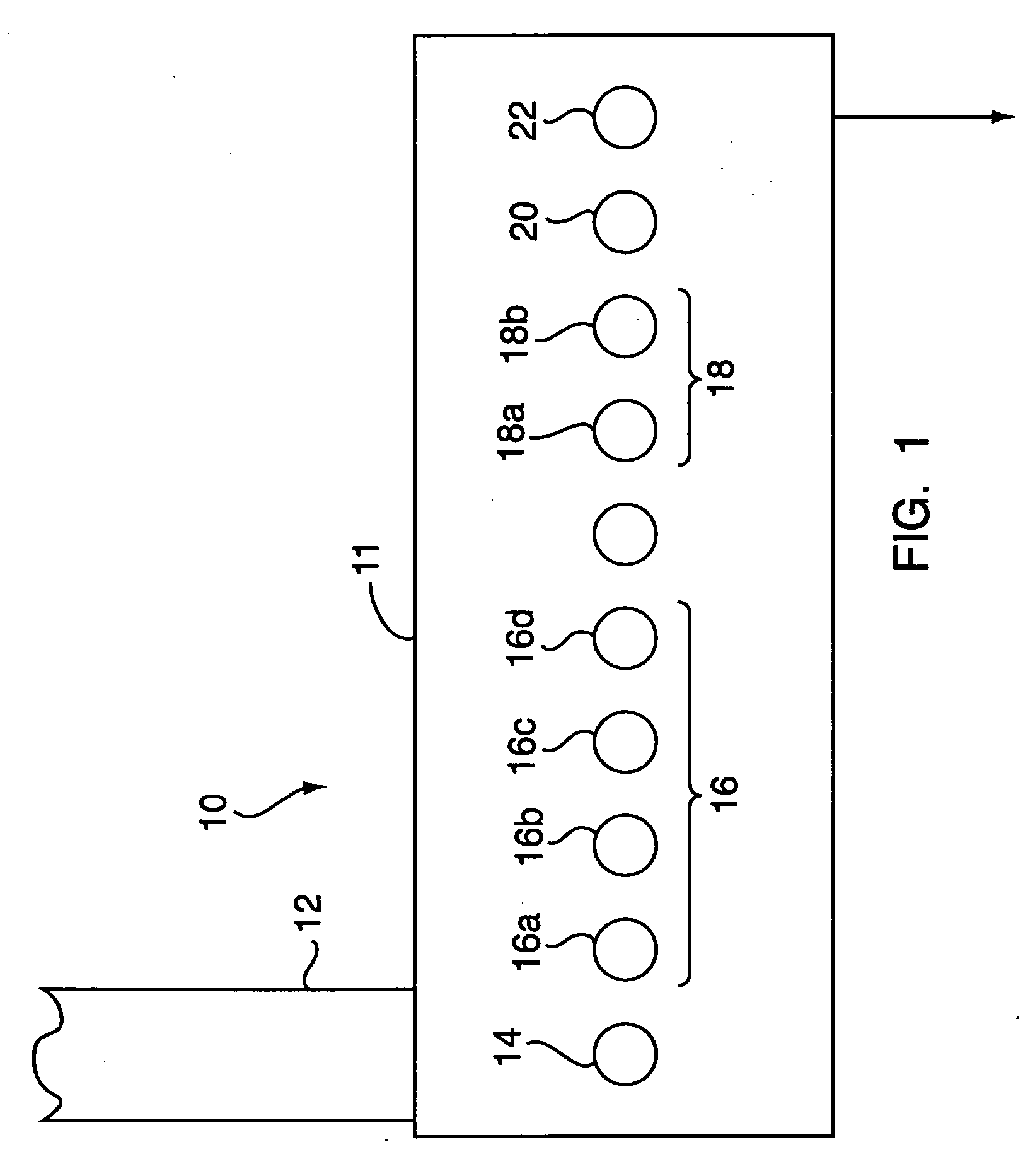
[0023] Referring to FIG. 1, a schematic diagram of the draw-iron-redraw manufacturing process in a transfer press is shown generally at 10 and is hereinafter referred to as “DIR process 10.” In the DIR process 10, cans are formed for use in battery cells as described above. Although the DIR process 10 as described below refers specifically to the forming of cans for alkaline battery cells, it should be understood that cans for other types of battery cells may be formed by the process described.

[0024] The DIR process is an improvement to a known transfer press process as described in the aforesaid U.S. Pat. No. 6,526,799. The DIR process is performed in a conventional transfer press 11, which may consist of multiple punch and die stations arranged inline, as depicted schematically in the drawing. Transfer press 11 is supplied with a strip of thin nickel plated steel 12. The feed mechanism is arranged to shift the strip from side to side to minimize scrap, using conventional feed mec...


PUM

PropertyMeasurementUnit
thicknessaaaaaaaaaa
lengthaaaaaaaaaa
diameteraaaaaaaaaa

Abstract

A process for producing a battery can in a transfer press comprises drawing a metal cup in a first station to form an elongated cylinder, ironing the elongated cylinder in a second station, and redrawing the elongated cylinder in a third station. In either or both the drawing and ironing steps, the cup or the elongated cylinder may be processed in more than one station. The process includes a final redraw station for redrawing the cylinder so as to roughen the inner surface of the battery can to improve its electrical properties.

Description

TECHNICAL FIELD [0001] This invention relates in general to battery cans, and, more particularly, to processes and systems for producing battery cans that provide superior battery performance. BACKGROUND OF THE INVENTION [0002] Alkaline electrochemical cells and batteries are utilized in a wide variety of applications to provide either a main source of power or back-up power to a wide variety of devices. These cells employ an alkaline electrolyte solution combined with a zinc anode and a manganese dioxide cathode. The battery cans are fabricated from thin metal sheeting and are typically manufactured in cylindrical shapes in standard sizes such as AA, AAA, 4A, C, D, etc. for well-known applications such as toys, flashlights, portable audio devices, and the like. [0003] In alkaline cells, the can itself serves as the cathode current collector. When incorporated into a circuit and used to provide a potential across a load, physical contact between the cathode and the can provides for ...

Claims


Application Information

Patent Timeline
Patent Type & Authority Applications(United States)
IPC IPC(8): H01M2/02B21C23/00B21D11/10
CPCB21D22/28B21D51/54H01M2/022H01M2/0225H01M6/08H01M50/107H01M50/56
Inventor BOUFFARD, RICHARD
Owner H & T BATTERY COMPONENTS USA
Why Eureka
Try Eureka