Apparatus for making threaded articles in a plastic injection molding process

a technology of injection molding and apparatus, which is applied in the field of mechanism of injection molding process for forming, can solve the problems of reducing production efficiency, contributing to component wear, and adding time to the molding cycle, so as to reduce the cost of ongoing maintenance, save time, and cost

Inactive Publication Date: 2007-01-02
CREATIVE MOLD SOLUTIONS
View PDF9 Cites 24 Cited by
  • Summary
  • Abstract
  • Description
  • Claims
  • Application Information

AI Technical Summary

Benefits of technology

[0029]The present invention is a redesigned system that saves time and reduces the cost of ongoing maintenance. The plastics industry has always searched for ways to make molded products faster, cheaper, better, at lower cost and with minimal maintenance. They are constantly searching for the lowest cost per part possible.
[0030]The design features and construction of this new invention provide ways to achieve each and every one of these goals. The invention is comprised of three (3) separate developments that all work together with results that can produce molded products faster, cheaper; better, at lower cost and with minimized maintenance. The three devices are:

Problems solved by technology

The unscrewing system as described adds time to the molding cycle, reduces production efficiencies, contributes to component wear and increases the maintenance costs involved with keeping a mold in operating condition.
Since unnecessary distance relates to unnecessary time and unnecessary component wear, this system contributes to lost time and increased costs.3. Due to the time required to return the cylinder and all components to their original position valuable production time is lost before another molding cycle can begin.4. Due to the unnecessary distance all components must travel while the cylinder is being returned to its original position, wear on bearings, bearing surfaces, dynamic seals and all moving components is doubled.
This increase in size may adversely affect the overall size of the mold to a point that it will require a larger molding machine.

Method used


Image

  • Apparatus for making threaded articles in a plastic injection molding process
  • Apparatus for making threaded articles in a plastic injection molding process
  • Apparatus for making threaded articles in a plastic injection molding process

Examples


Embodiment Construction

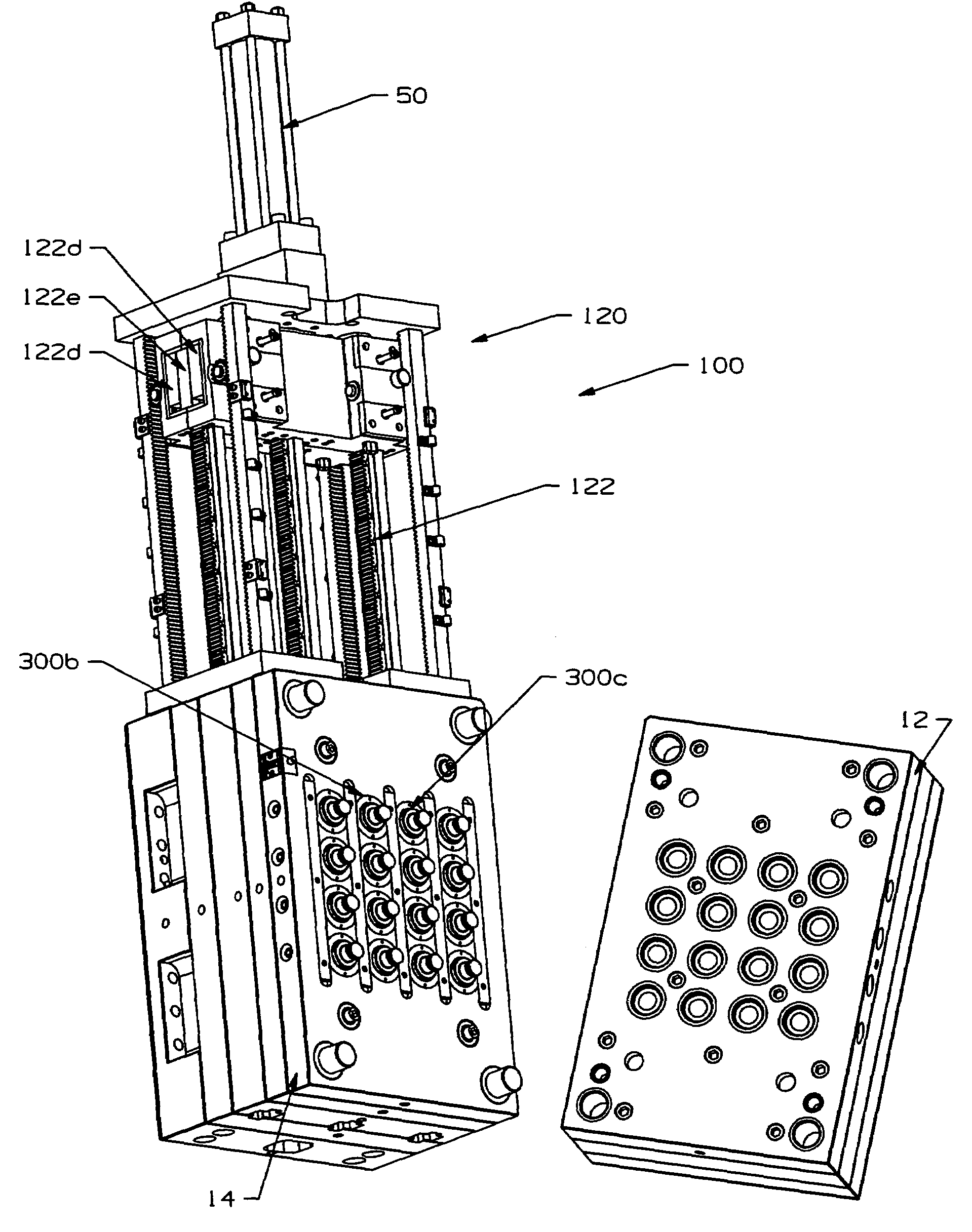
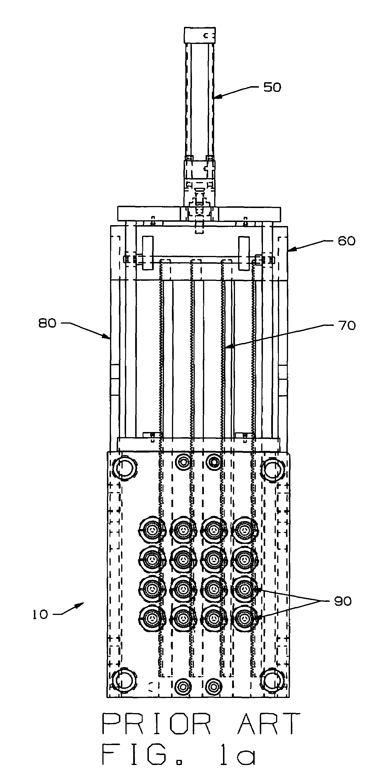
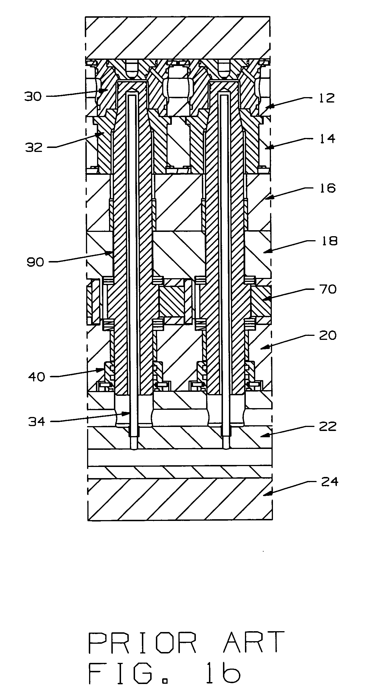
[0063]Referring now to the drawings, FIGS. 1a–1e depict a typical arrangement of components of an example of a prior art mold system described in the Background of the Invention section above. These drawings include textual indicia of the major parts to more readily familiarize a reader with the operating parts of a prior art molding system. Some of the primary components shown are a hydraulic cylinder 50, a crosshead assembly 60, the racks 70, advance bars 80, an unscrewing mold 10, cavity insert 30, cavity plate 12, stripper plate 14, rack plate 18, bubbler plate 22, the molded part to be manufactured (FIG. 1e), a stripper ring 32, a bearing retainer plate 20, stationary plate 16, an unscrewing core 90, a water seal bushing 40 and a bubbler tube 34. As well as the cam mechanism or assembly, which enables the separation of the stripper plate 14 from the underlying stationary plate 16.

[0064]Referring to FIGS. 2–17 in general, we will now discuss the major components of the various e...


PUM

PropertyMeasurementUnit
clamping pressureaaaaaaaaaa
speedaaaaaaaaaa
rotationaaaaaaaaaa

Abstract

A Bi-directional rack assembly that rotates one column of threaded cores and unscrews threaded closures while moving in the forward direction. The Bi-directional rack then mechanically changes position to engage an adjacent column of rotating threaded cores and at the end of a second molding cycle rotates the threaded cores and unscrew threaded closures while moving in the reverse (reset) direction. A set of timed-advance devices are engaged by a smaller pinion gear and idler gear assemblies to the Bi-directional rack and as the Timed-Advance devices are activated, they allow pneumatic pistons to advance the stripper plate in time with the threaded closures as they are being unscrewed from the threaded cores. A second “rapid advance” pneumatic piston eliminates the need for an external rapid rise camming feature. A rotating core comprising a stock, rotating core, a stock water-seal insert and a custom core top.

Description

FIELD OF THE INVENTION[0001]The invention relates to a mechanism in the injection molding process for forming threaded molded parts and for assemblies that are more easily maintained, repaired and replaced at reduced associated costs.BACKGROUND OF THE INVENTION[0002]Several methods to remove plastic thread forms from injection molds upon completion of the injection molding processes exist. The most common methods are as follows:[0003]1. Unscrewing of the threads using rotating cores actuated by hydraulically operated racks or other mechanisms. The rotating cores are located in fixed locations and eject (push) the molded thread forms from the mold by rotation of the cores and a mechanically actuated, mechanically timed (cam action) stripper plate.[0004]2. Unscrewing the molded part from a stationary (fixed) core through the use of a hydraulically actuated rack rotating a pinion assembly, which rotates “ratchet rings”, for example, a Husky Rotating Ratchet Ring system. Ejection is don...

Claims


Application Information

Patent Timeline
Patent Type & Authority Patents(United States)
IPC IPC(8): B29C33/04B29C45/44
CPCB29C45/262B29C45/7312Y10S425/058B29L2031/565
Inventor SEIDELMAN, GERALDCHALCRAFT, ALBERT BRUCE
Owner CREATIVE MOLD SOLUTIONS
Why Eureka
Try Eureka