Linear vibration-wave motor

a vibration-wave motor and linear technology, applied in piezoelectric/electrostrictive/magnetostrictive devices, mountings, instruments, etc., can solve the problem of high probability of quality problems, and achieve the effect of better ensuring performance as a single item

Active Publication Date: 2015-07-16
CANON KK
View PDF1 Cites 15 Cited by
  • Summary
  • Abstract
  • Description
  • Claims
  • Application Information

AI Technical Summary

Benefits of technology

[0006]The present invention provides a stable-quality linear vibration-wave motor whose performance as a single item is guaranteed.
[0008]The present invention can implement a stable-quality linear vibration-wave motor whose performance as a single item can be better guaranteed.

Problems solved by technology

A problem in quality is highly likely to occur.

Method used


Image

  • Linear vibration-wave motor
  • Linear vibration-wave motor
  • Linear vibration-wave motor

Examples


Embodiment Construction

[0016]Preferred embodiments of the present invention will now be described in detail in accordance with the accompanying drawings.

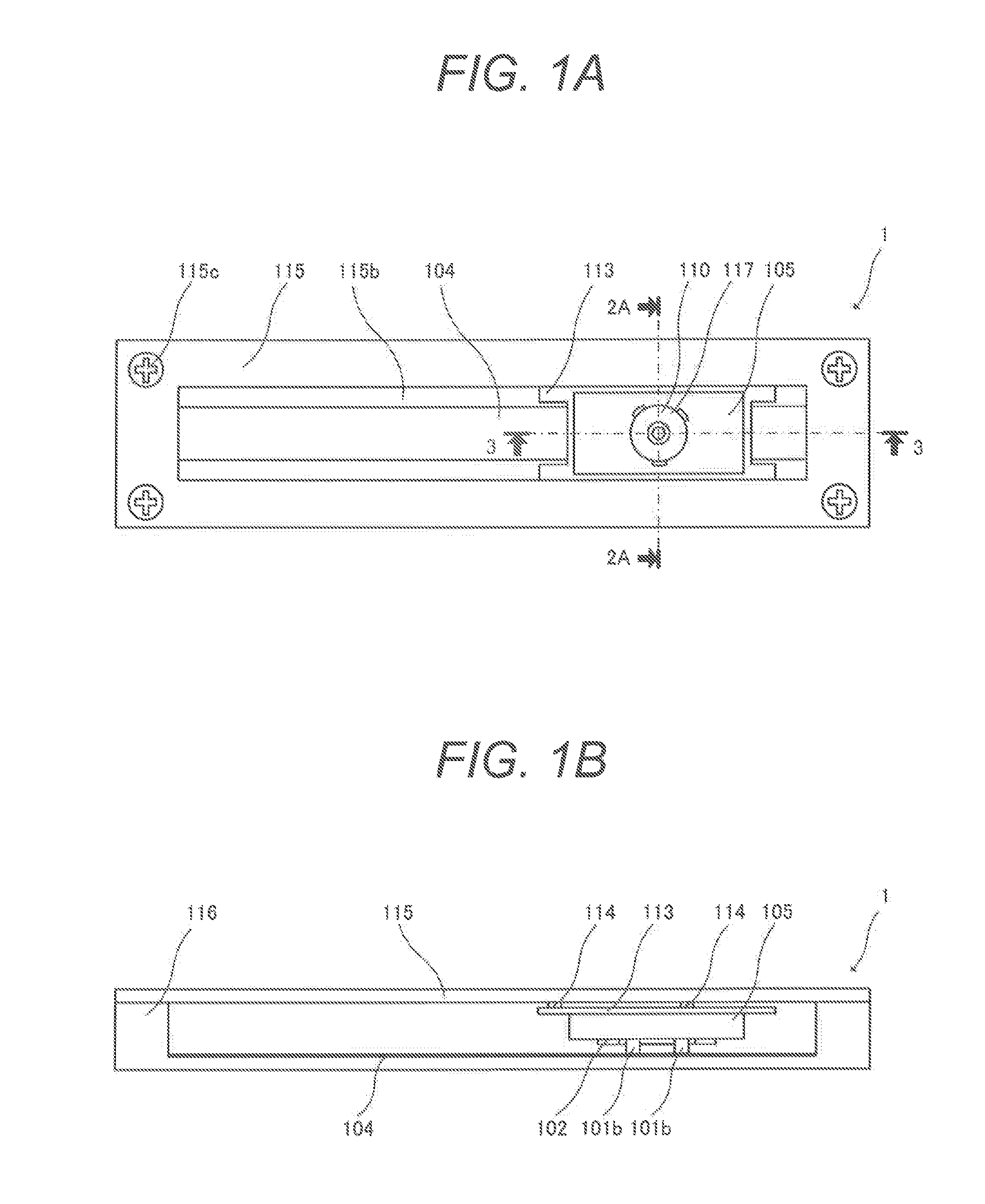
[0017]FIGS. 1A and 1B show the outer appearance of a linear ultrasonic motor 1 as an embodiment of a linear vibration-wave motor according to the present invention that functions as a focus driving source for an optical device such as the lens barrel for a lens and applies a driving force. FIG. 1A is a plan view, and FIG. 1B is a front view.

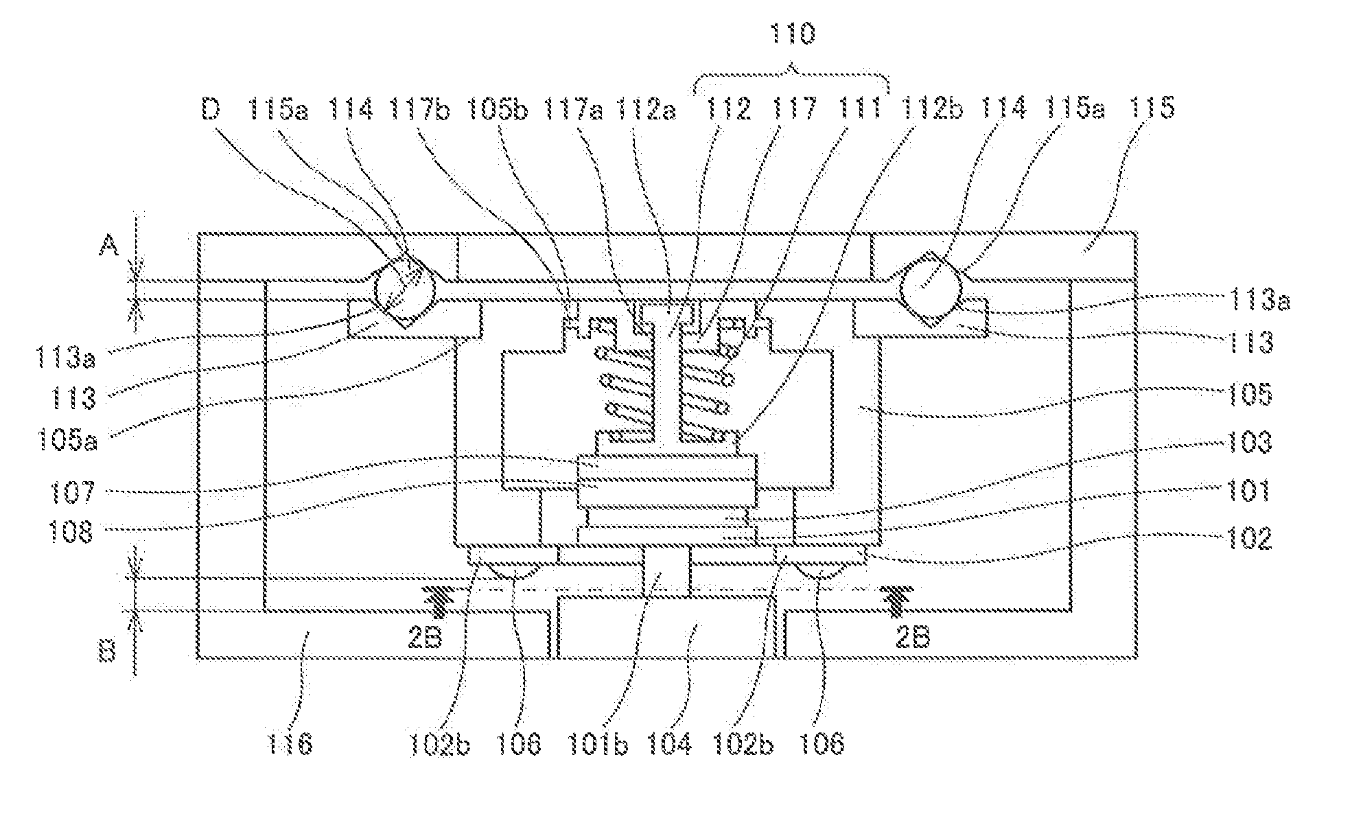
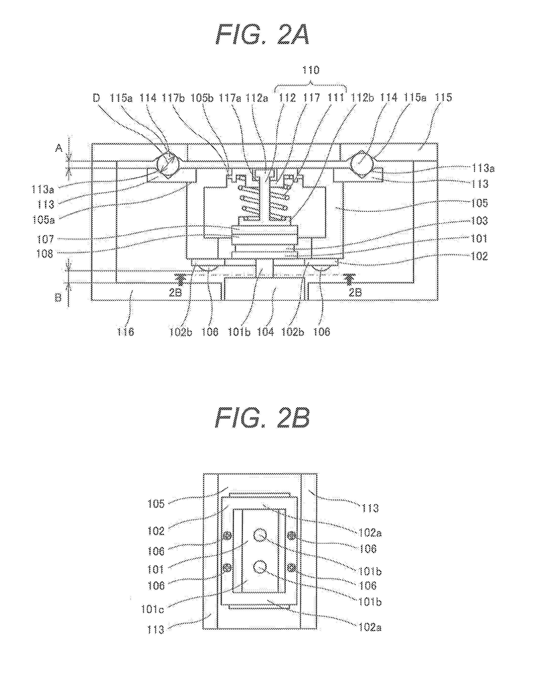
[0018]FIGS. 2A and 2B are sectional views showing the main parts of the linear ultrasonic motor 1. FIG. 2A shows a section perpendicular to the direction of the driving force to the lens barrel as a sectional view taken along a line 2A-2A in FIG. 1A. FIG. 2B shows a sectional view taken along a line 2B-2B in FIG. 2A. Members other than a vibrator, a connecting member, a vibrator support member, and a moving plate are not illustrated.

[0019]FIG. 3 is a sectional view showing the main part of the linear ultrasonic motor 1...


PUM


Abstract

A linear vibration-wave motor being configured to apply a driving force to a lens barrel of an optical device includes a vibrator being operable to excite a vibration, a member to be contacted contacting the vibrator, the vibrator being arranged to move in a direction of the driving force with respect to the member to be contacted upon exciting the vibration, a vibrator support being fixed to the lens barrel and configured to support the vibrator, a pressurization member being operable to press the vibrator against the member to be contacted, a unit cover member including an opening extending in the direction of the driving force, and a unit base member having fixed thereto the member to be contacted and the unit cover member. The pressurization member is detachable from the vibrator support via the opening.

Description

BACKGROUND OF THE INVENTION[0001]1. Field of the Invention[0002]The present invention relates to a vibration-wave motor and, more particularly, to a linear vibration-wave motor unit including a linear ultrasonic motor or the like that can be incorporated in an optical device.[0003]2. Description of the Related Art[0004]There has conventionally been known a technique of driving a sliding member by pressurizing a vibrator configured to vibrate periodically upon application of a high-frequency voltage, and bringing the vibrator into contact with the sliding member in a linear vibration-wave motor of this type.SUMMARY OF THE INVENTION[0005]However, in a conventional technique disclosed in Japanese Patent Application Laid-Open No. 2006-187114, a component is directly incorporated in the lens barrel of an optical device. For this reason, only characteristics in an actual load state can be guaranteed, and the no-load characteristics of a linear vibration-wave motor unit and the like cannot...

Claims


Application Information

Patent Timeline
Patent Type & Authority Applications(United States)
IPC IPC(8): H02N2/08H02N2/04H02N2/02
CPCH02N2/08H02N2/04H02N2/026G02B7/10H02N2/0055G02B7/005
Inventor YAMAMOTO, HARUSHIGE
Owner CANON KK
Why Eureka
Try Eureka