Ramped Connector And Blade For Use With Rotary Head Assembly

a technology of rotary head assembly and connector, which is applied in the direction of metal working apparatus, agriculture tools and machines, etc., can solve the problems of affecting the cutting accuracy of the rotary head assembly, etc., to achieve the removal of the cutting member, the cutting member is simple and efficient, and the insertion is quick and easy.

Active Publication Date: 2015-07-23
JEREZ ORLANDO
View PDF14 Cites 15 Cited by
  • Summary
  • Abstract
  • Description
  • Claims
  • Application Information

AI Technical Summary

Benefits of technology

[0006]From the foregoing, it is apparent there is still a great and long-felt need for a rotary apparatus, in particular a rotary head assembly, that provides quick and easy insertion of a cutting member in order to resume operation as well as simple and efficient removal of the cutting member when replacing it. The present invention addresses the foregoing need, amongst other needs, in a highly unique and facile way. Thus, in one aspect, the present invention provides a novel rotary apparatus, particularly a rotary head assembly from which a cutting member may extend. Particularly, in at least one of its aspects, this invention provides quick and easy insertion of a cutting member in order to resume operation of the rotary apparatus. In another aspect, the invention also facilitates removal of a cutting member during change out, so that there is no need to disassemble the rotary head assembly of the rotary apparatus, as required in other known trimmer apparatuses. The cutting member of the present invention can be flexible (e.g. wires, strands, etc.), semi-rigid (e.g. plastic blades), or rigid (e.g. metal blades) and may be made of any material and in any shape capable of cutting unwanted plants such as weeds. Non-limiting examples of cutting member materials include plastics (e.g. nylon), metals, metal alloys, and combinations thereof.

Problems solved by technology

However, such weed trimming apparatuses have certain drawbacks which have gone largely unaddressed in this technical field.
Stress on these apparatuses' trimming lines will cause it break from time to time during use.
Because of their designs, the trimmer lines often get twisted, tangled or buried within the spool making it difficult to dispense the proper line length for cutting.
This process is difficult, labor intensive and highly time consuming.
As the blades become dull or the trimmer lines break, often times, it require additional tools and / or a lot of time to replace the worn or broken pieces.

Method used


Image

  • Ramped Connector And Blade For Use With Rotary Head Assembly
  • Ramped Connector And Blade For Use With Rotary Head Assembly
  • Ramped Connector And Blade For Use With Rotary Head Assembly

Examples


Embodiment Construction

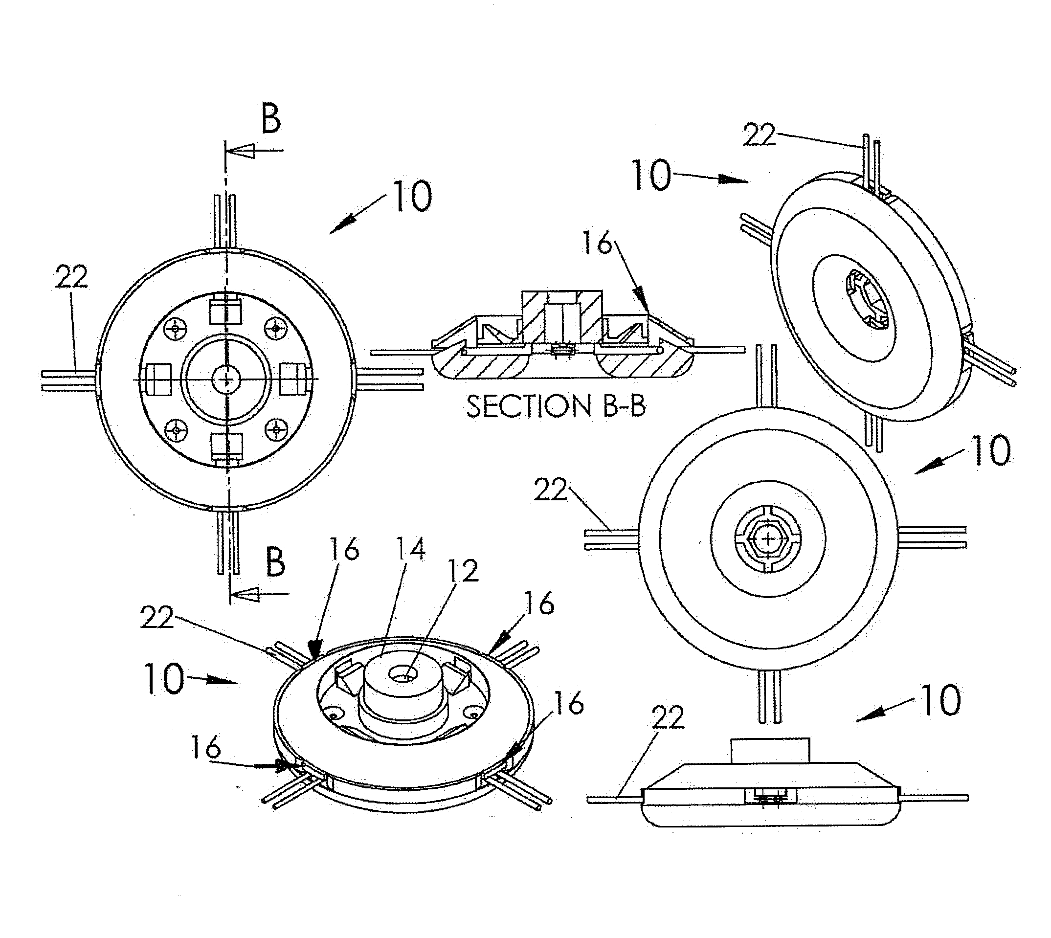
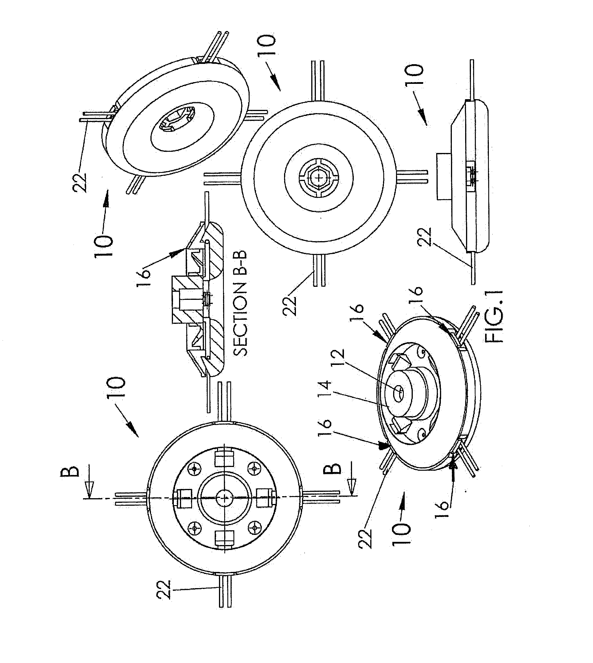
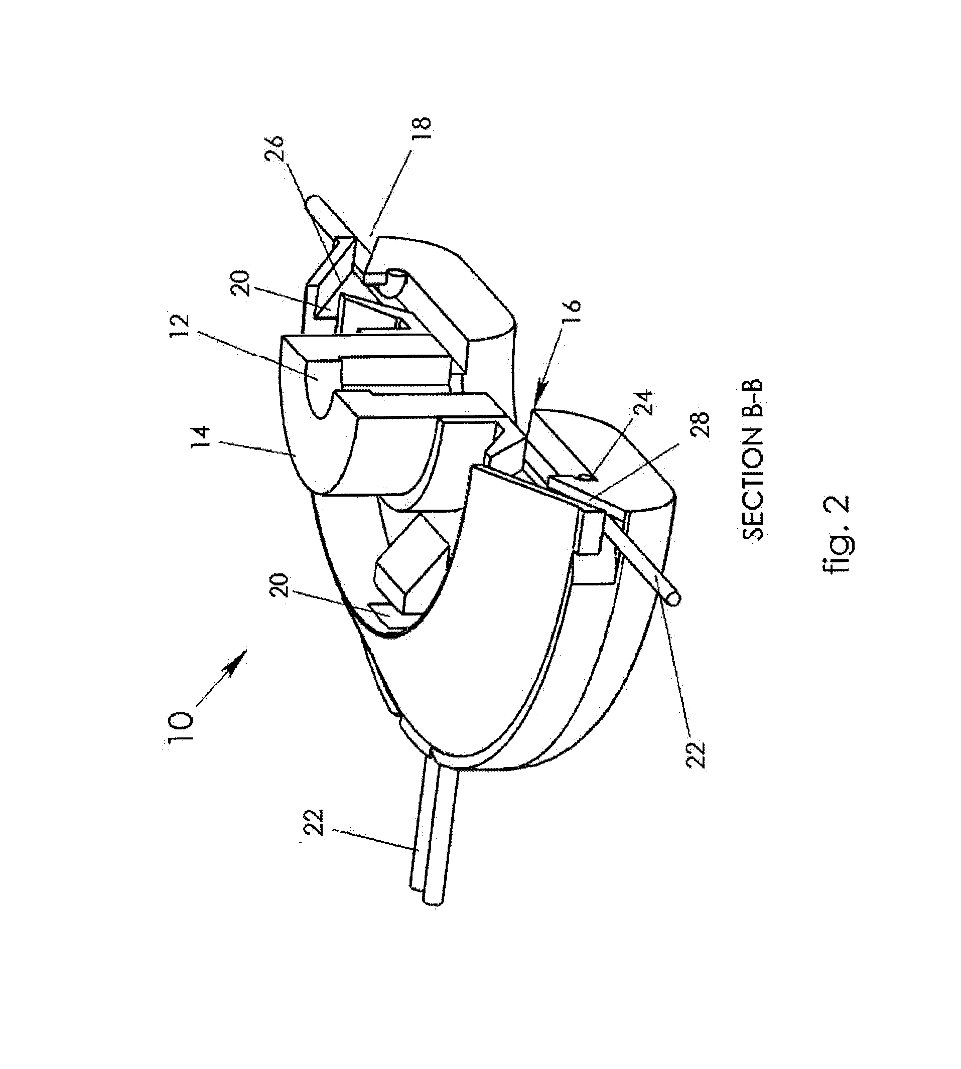
[0046]Illustrative implementations of the invention are described below as they might be employed in the construction and use of a rotary apparatus and related method according to at least one implementation of the present invention. It will be of course appreciated that in the development of such an actual implementation, numerous implementation-specific decisions must be made to achieve the developers' specific goals, such as compliance with system-related and business-related constraints, which will vary from one implementation to another. Moreover, it will be appreciated that such a development effort might be complex and time-consuming, but would nevertheless be a routine undertaking for those of ordinary skill in the art having the benefit of this disclosure. In the detailed description below, general discussion of alternative steps, configurations, features and / or components may employ reference to numbered components identified in the accompanying figures. However, it should...


PUM


Abstract

A rotary head assembly apparatus, and a cutting blade for use on trimmer rotary head assemblies are disclosed. The rotary head assembly apparatus is configured to easily replace cutting members necessary to cut unwanted plants. The cutting blade is for use on trimmer rotary head assemblies configured to cut unwanted vegetation.

Description

REFERENCE TO RELATED APPLICATIONS[0001]This application is a continuation-in-part of copending and commonly-owned International Patent Application No. PCT / US2013 / 053801, filed on Aug. 6, 2013, which claims priority to U.S. Provisional Application No. 61 / 681,304, filed on Aug. 9, 2012. This application also claims the benefit of U.S. Provisional Application No. 62 / 041,945, filed Aug. 26, 2014. Each patent application identified above is incorporated here by reference in its entirety.TECHNICAL FIELD[0002]The present disclosure relates to rotary head assembly apparatuses and cutting blades designed for use with rotary head assemblies. More particularly, the present disclosure relates to rotary head assembly apparatuses configured to easily replace cutting members necessary to cut unwanted plants and cutting blades therefor.BACKGROUND[0003]Presently, there are trimming apparatuses known in the art having a rotatable, attachable head for attachment to a powered device, with the head carr...

Claims


Application Information

Patent Timeline
Patent Type & Authority Applications(United States)
IPC IPC(8): A01D34/416
CPCA01D34/416A01D34/4166
Inventor JEREZ, ORLANDO
Owner JEREZ ORLANDO
Why Eureka
Try Eureka