
Ladder rest and restraining device

a technology of restraint device and ladder, which is applied in the direction of ladders, building construction, construction, etc., can solve the problems of ladder sliding, unstable and possible injury, and achieve the effect of preventing significant sideways motion, preventing downward slippage, and efficiently secured

Active Publication Date: 2015-07-23
SPRINGFIELD CONSTR LLC
View PDF0 Cites 19 Cited by
  • Summary
  • Abstract
  • Description
  • Claims
  • Application Information

AI Technical Summary

Benefits of technology

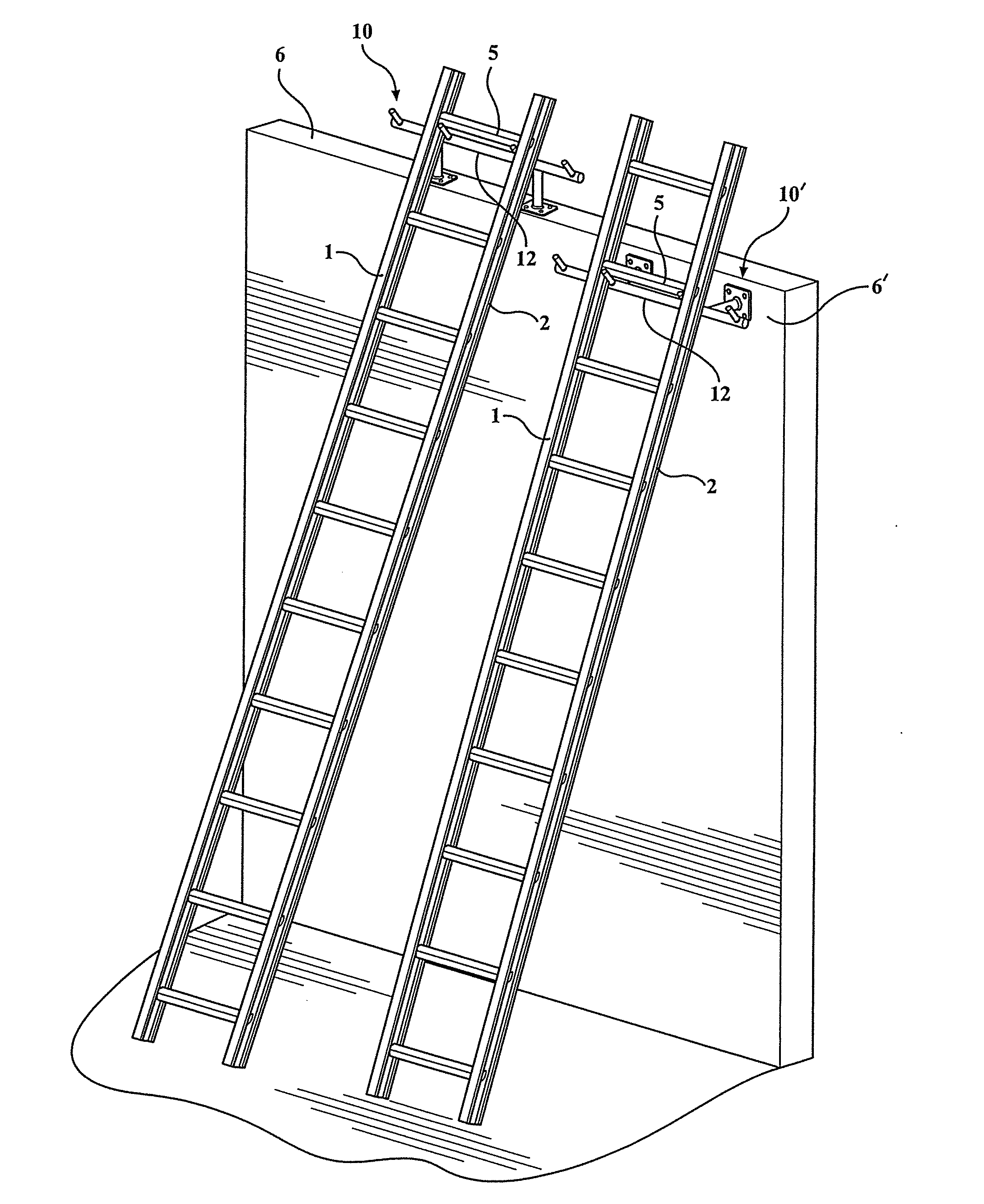
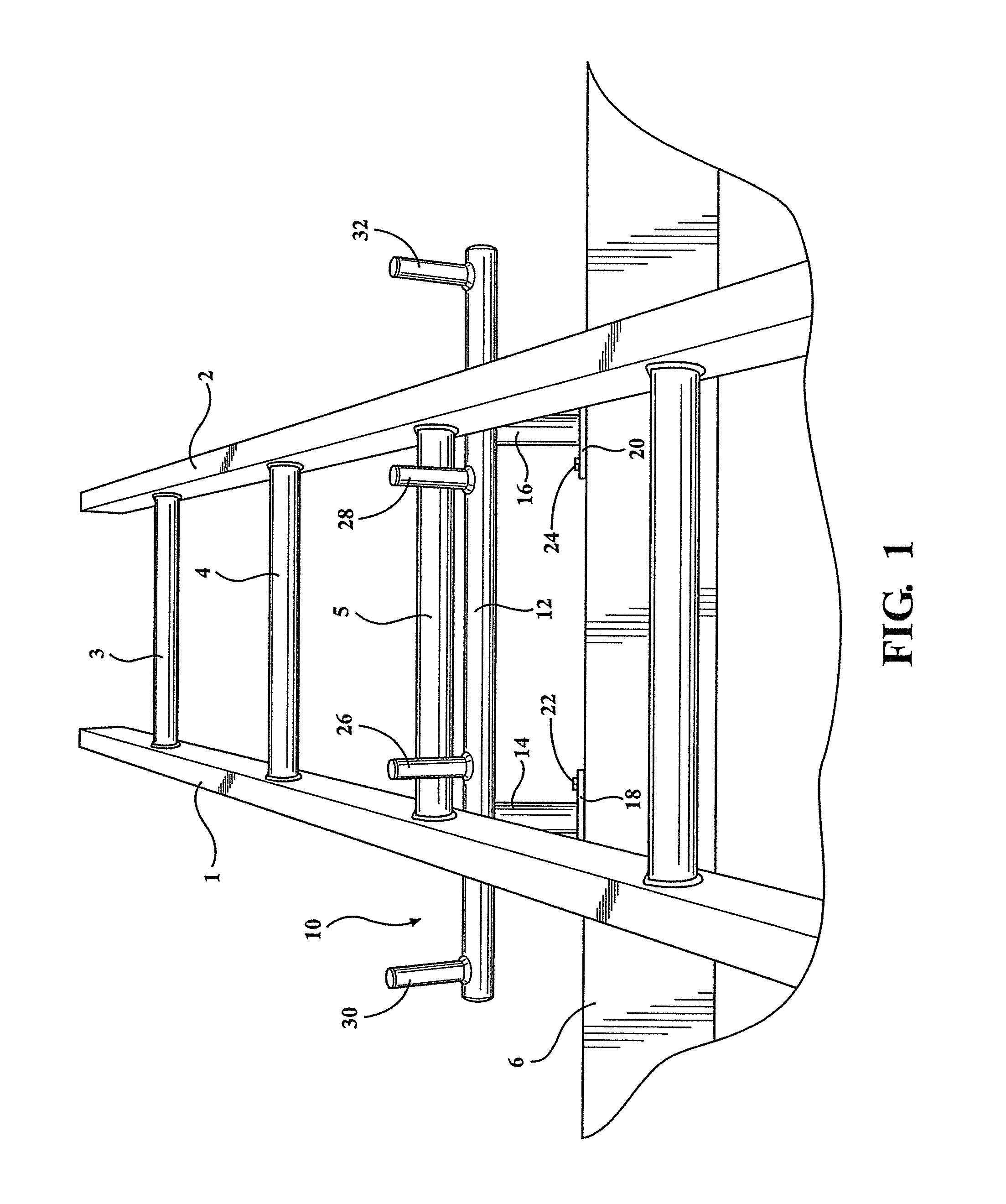
The present invention is a ladder guide or stabilizer that can be permanently attached to a roof or other structure. It prevents the ladder from moving sideways or slipping downward by providing resistance against the ladder's side rails and a rung of the ladder. The guide can be easily attached to vertical, horizontal, or intermediate angled surfaces on the elevated structure. The guide includes multiple restraining members that engage the ladder to prevent it from moving. One sub-plurality of the restraining members limits lateral displacement of the ladder's stanchion members, and another sub-plurality limits sideways motion of the ladder's side rails. Overall, the ladder guide ensures safety and stability when using the ladder.

Problems solved by technology

Although ladders often provide treads on their base for traction at the base end, they are not permanently affixed, and the base of the ladder, when weight is on the ladder, may slide, either sideways or outwardly, resulting in instability, downward sliding of the ladder, and possible injury to any person using the ladder.
Likewise, at the roof's edge, the surfaces may not be conducive to holding the ladder in one spot and, again, when a person is using the ladder, particularly with heavier loads or when weight shifts take place when gaining access to, or exiting from, a roof, forces may be exerted on the ladder to cause it to move sideways or downwardly, again providing instability and possible injury.
Even this, however, may not be sufficient if enough force is exerted at the top of the ladder to cause the ladder to move when a person at ground level has a poor purchase point, in terms of being a fulcrum, to prevent motion caused by significant force at the upper end.

Method used


Image

  • Ladder rest and restraining device
  • Ladder rest and restraining device
  • Ladder rest and restraining device

Examples


Embodiment Construction

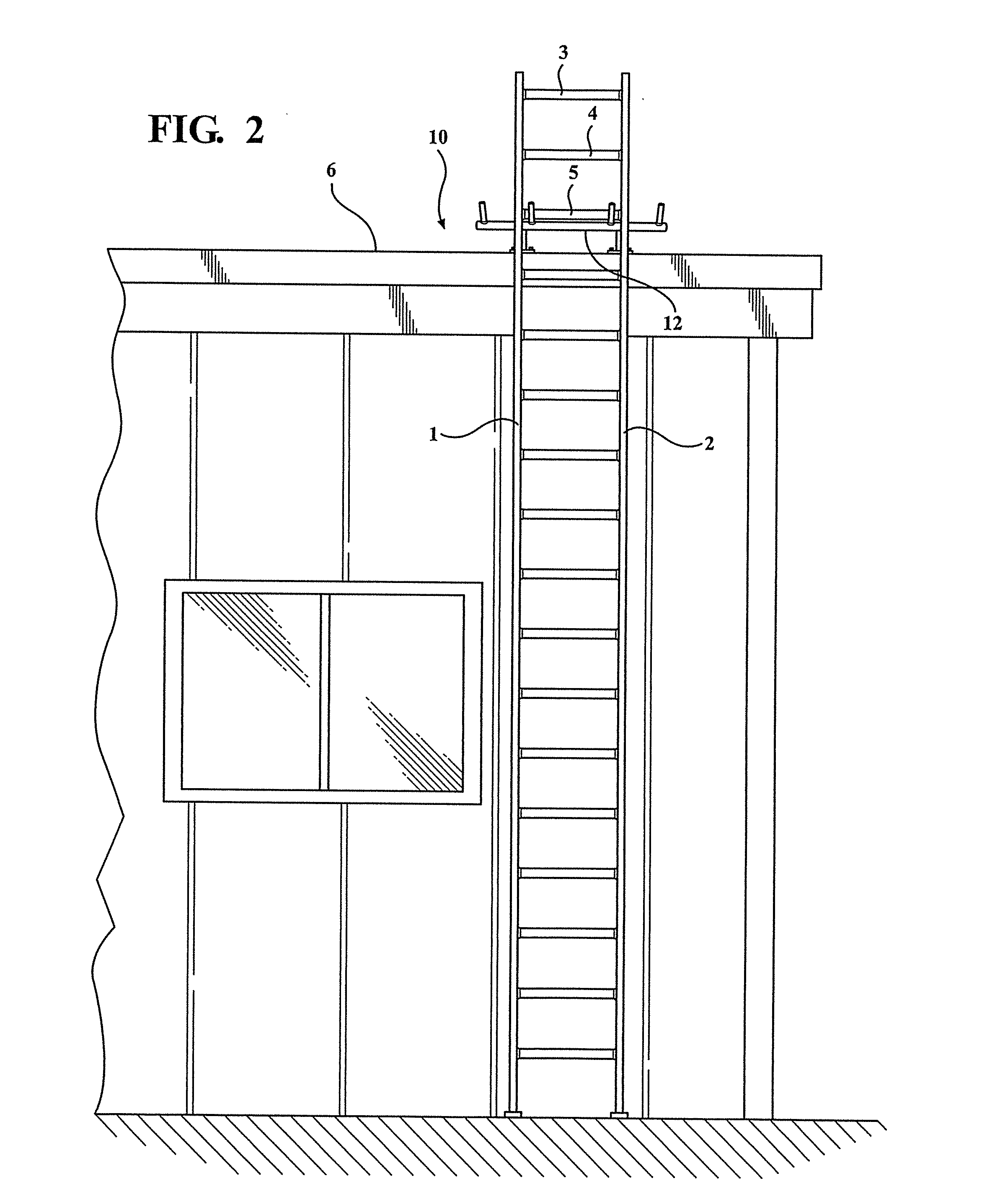
[0023]As will be further described with reference to FIGS. 1-4, the present invention discloses a number of mounting arrangements associated with a ladder support and restraining device. The present device is particularly suited for securing to any of horizontal, vertical or angular surfaces associated with an elevated structure, the advantage of which being that it provides both underside support to a selected interconnecting rung of the ladder (typically including but not limited to an extension ladder), as well additionally restraining lateral displacement of the ladder.

[0024]As shown in FIG. 1, the existing ladder includes a pair of outer and length extending sides or stanchions 1 and 2, between which are supported in interconnecting and spaced apart fashion a plurality of climbing rungs 3, 4, 5, et seq. Although shown in singular fashion, it is well understood that the convention ladder can further include the extension variety in which a pair of inter-displaceable and ratchet ...


PUM


Abstract

A ladder rest and restraining device is provided for the edge of a roof or other elevated structure which is regularly or periodically accessed by means of an extension ladder or other similar device. The device may be permanently or removably mounted on the edge of the roof or structure where the ladder is normally positioned, to limit movement of the ladder horizontally, sideways, as well as vertically downward. The device includes an elongated primary support, a pair of legs extending from spaced apart locations of the primary support, the legs terminating in mounting feet. A plurality of restraining members extend from additional spaced apart locations of the primary support. The mounting feet are adapted to engage any of horizontal, vertical or angled surfaces associated with the elevated structure, such that a first sub-plurality of the restraining members are adapted to abut an underside of a selected rung to prevent downward movement of the ladder. A further sub-plurality of the restraining members are outwardly spaced from the first sub-plurality and adapted to limiting lateral displacement of the stanchion members in each of opposite directions.

Description

CROSS-REFERENCE TO RELATED APPLICATIONS[0001]This application claims the benefit of U.S. Provisional Application 61 / 930,691 filed on Jan. 23, 2014, the contents of which are incorporated herein in its entirety.FIELD OF THE INVENTION[0002]The present invention relates generally to ladder support and restraint devices. More specifically, the present invention teaches a ladder rest and restraining device for utilization with a conventional extension ladder having a pair of elongated stanchion or side members and a plurality of climbing rungs mounted perpendicularly between. The restraint device of the present invention has a rigid primary horizontal member, mounting supports extending from the primary member for affixing to an elevated structure, and a plurality of restraining members projecting outwardly from the primary support member for abutting both the horizontal stanchions of the conventional ladder as well as providing underside support to a selected interconnecting climbing ru...

Claims


Application Information

Patent Timeline
Patent Type & Authority Applications(United States)
IPC IPC(8): E06C7/48E06C1/04
CPCE06C1/04E06C7/48E06C7/486
Inventor UMLOR, TERRENCE L.SEARS, TODD T.
Owner SPRINGFIELD CONSTR LLC
Learn More