
Optical line terminal communication method and device with data structure

a technology of optical line terminals and data structures, applied in the direction of electromagnetic network arrangements, wavelength-division multiplex systems, electrical apparatus, etc., can solve the problems of multi-olt pon systems that present complications in the coordination and control of various olts

Active Publication Date: 2015-07-23
FUTUREWEI TECH INC
View PDF8 Cites 39 Cited by
  • Summary
  • Abstract
  • Description
  • Claims
  • Application Information

AI Technical Summary

Benefits of technology

The present invention provides a way to manage the discovery and switching of optical network units (ONUs) when a new ONU is being added or when an existing ONU needs to be moved around in a network. This is particularly useful in a system where multiple optical line terminals (OLTs) are used to transmit data over a single network. This invention helps to ensure that new or moved ONUs are quickly detected and connected to the correct OLT port, which can save time and improve efficiency.

Problems solved by technology

However, a multi-OLT PON system presents complications in the coordination and control of the various OLTs.

Method used


Image

  • Optical line terminal communication method and device with data structure
  • Optical line terminal communication method and device with data structure
  • Optical line terminal communication method and device with data structure

Examples


Embodiment Construction

[0022]Reference will now be made in detail to the various embodiments of the present disclosure, examples of which are illustrated in the accompanying drawings. While described in conjunction with these embodiments, it will be understood that they are not intended to limit the disclosure to these embodiments. On the contrary, the disclosure is intended to cover alternatives, modifications and equivalents, which may be included within the spirit and scope of the disclosure as defined by the appended claims. Furthermore, in the following detailed description of the present disclosure, numerous specific details are set forth in order to provide a thorough understanding of the present disclosure. However, it will be understood that the present disclosure may be practiced without these specific details. In other instances, well-known methods, procedures, components, and circuits have not been described in detail so as not to unnecessarily obscure aspects of the present disclosure.

[0023]A...


PUM


Abstract

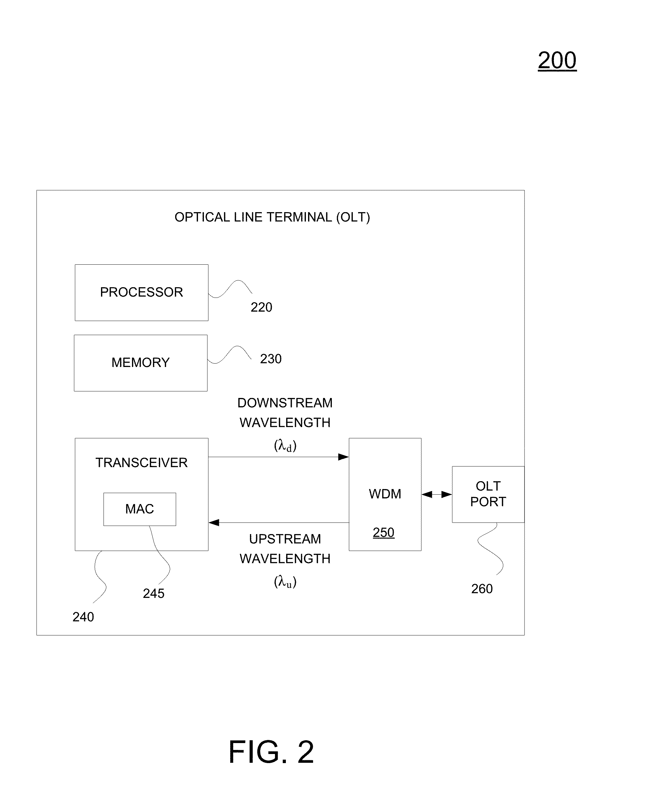
An optical line terminal (OLT) coupled to a plurality of optical network units (ONUs) through a passive optical network (PON). The OLT includes a transceiver configured to communicate via a management channel of a communication network with a plurality of OLTs. The communication includes sending or receiving a notification, wherein the notification includes the following: a source OLT identifier associated with a source OLT sending the notification, wherein the source OLT is configured to communicate over a first channel at a first wavelength of the PON; a destination OLT identifier associated with a destination OLT receiving the notification, wherein the destination OLT is configured to communicate over a second channel at a second wavelength of the PON; and an ONU identifier associated with a first ONU associated with the notification.

Description

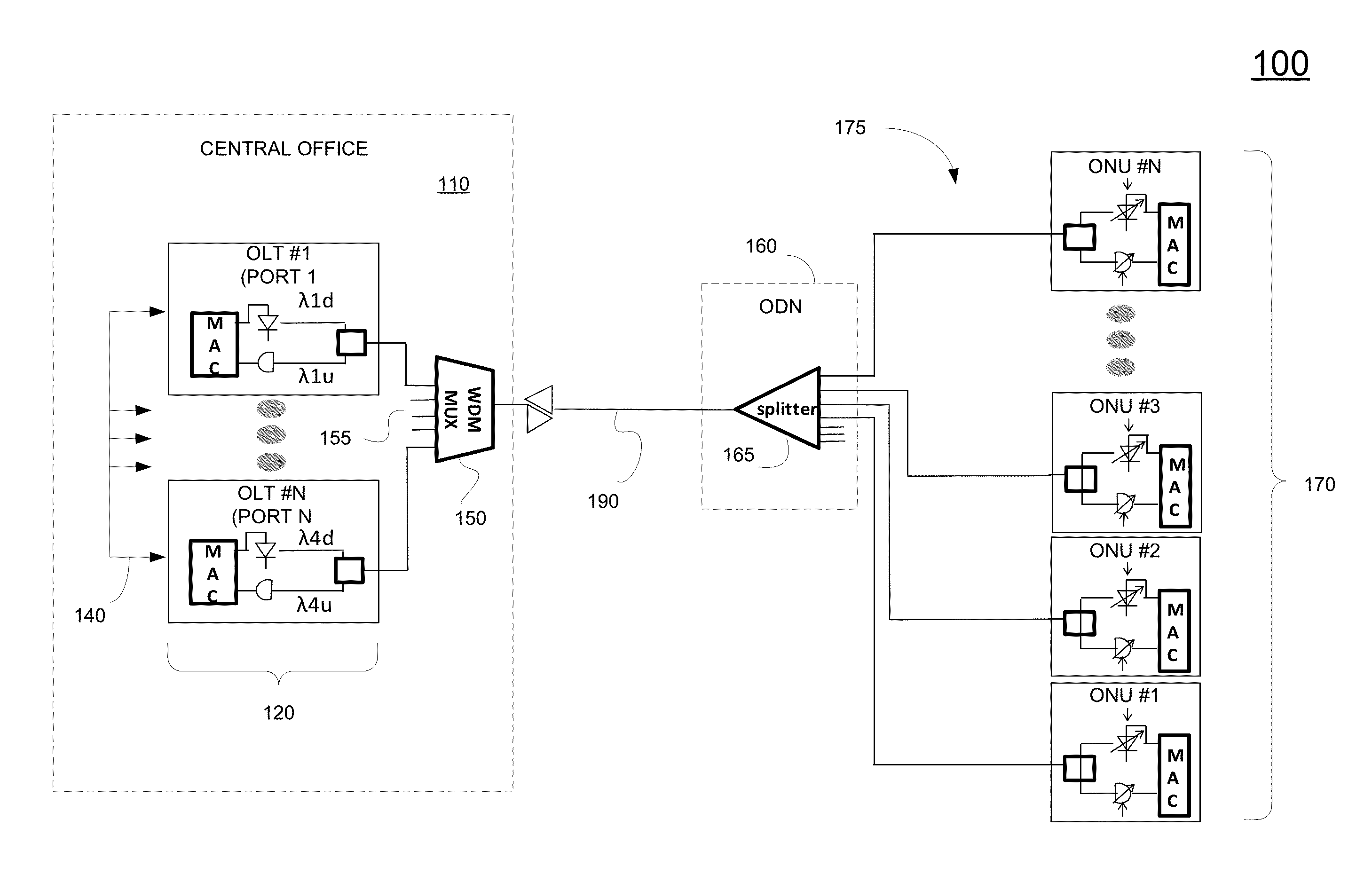
CROSS REFERENCE TO RELATED APPLICATIONS[0001]The present application claims priority to and the benefit of the commonly owned, provisional patent application, U.S. Ser. No. 61 / 930,886, entitled “OPTICAL LINE TERMINAL COMMUNICATION DATA STRUCTURE,” with filing date Jan. 23, 2014, and having attorney docket number HW-91014171US01, which is herein incorporated by reference in its entirety.BACKGROUND[0002]A passive optical network (PON) is one system for providing network access over “the last mile.” For example, the PON is a telecommunications network that includes a point-to-multi-point (P2MP) network and is comprised of an optical line terminal (OLT) at the central office, an optical distribution network (ODN), and a plurality of optical network units (ONUs) at the customer premises.[0003]The evolution for PON includes asynchronous transfer mode PON (APON), which evolved into Broadband PON (BPON), which is backward compatible with APON, which is defined by the International Telecommu...

Claims


Application Information

Patent Timeline
Patent Type & Authority Applications(United States)
IPC IPC(8): H04J14/02
CPCH04J14/023H04J14/0275H04J14/0282H04J14/0256H04B10/27H04J14/0257
Inventor LUO, YUANQIUGAO, BOEFFENBERGER, FRANK
Owner FUTUREWEI TECH INC
Learn More