
Visual guidance system

a visual guidance and system technology, applied in the direction of navigation instruments, process and machine control, instruments, etc., can solve the problems of affecting the operation of the operator, the outside edge of the implement is difficult to predict, and the operator is unable to control the vehicle and implement, etc., to achieve convenient and efficient

Inactive Publication Date: 2015-07-30
EDELEN BRIAN R
View PDF2 Cites 5 Cited by
  • Summary
  • Abstract
  • Description
  • Claims
  • Application Information

AI Technical Summary

Benefits of technology

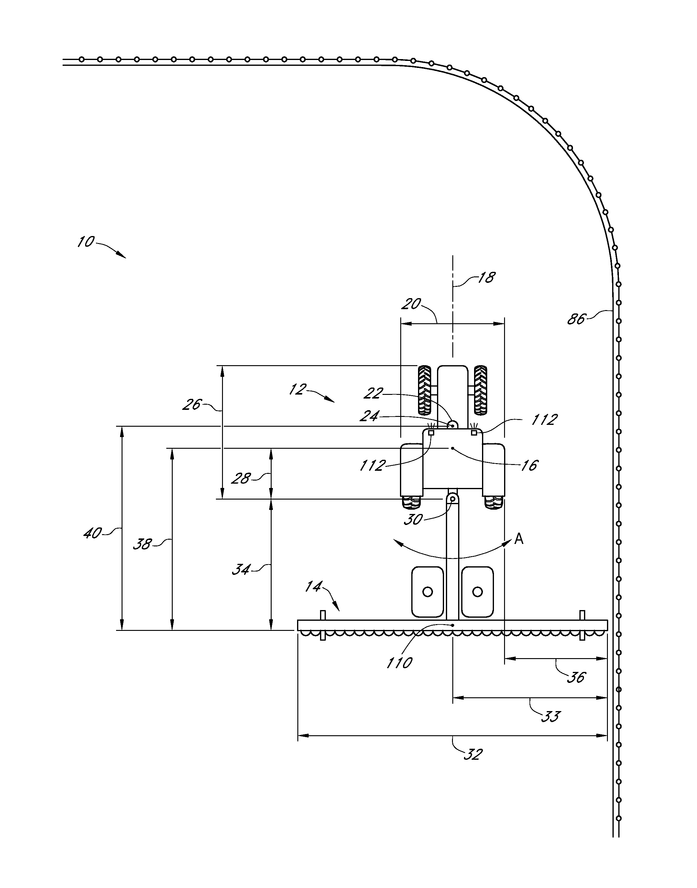
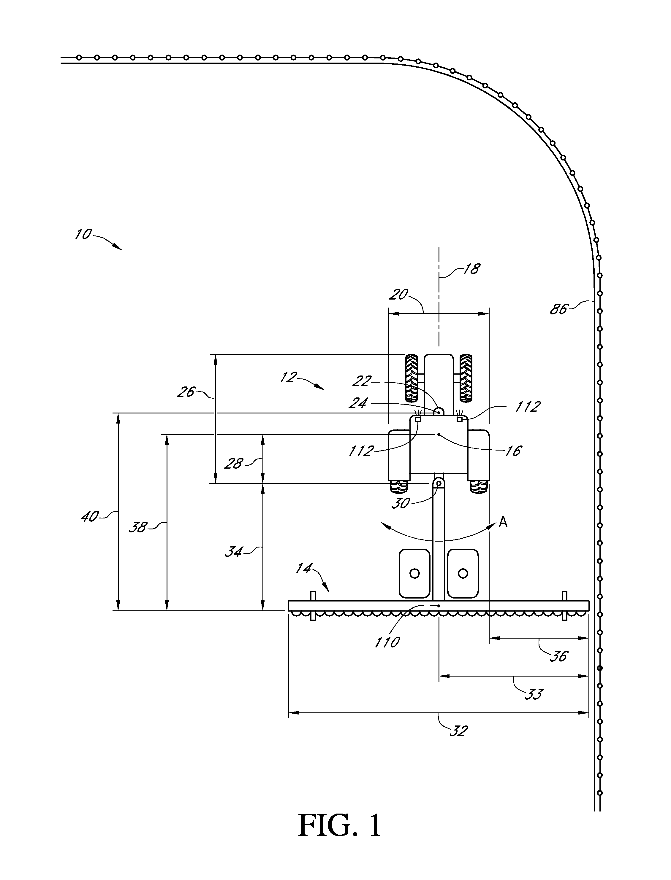
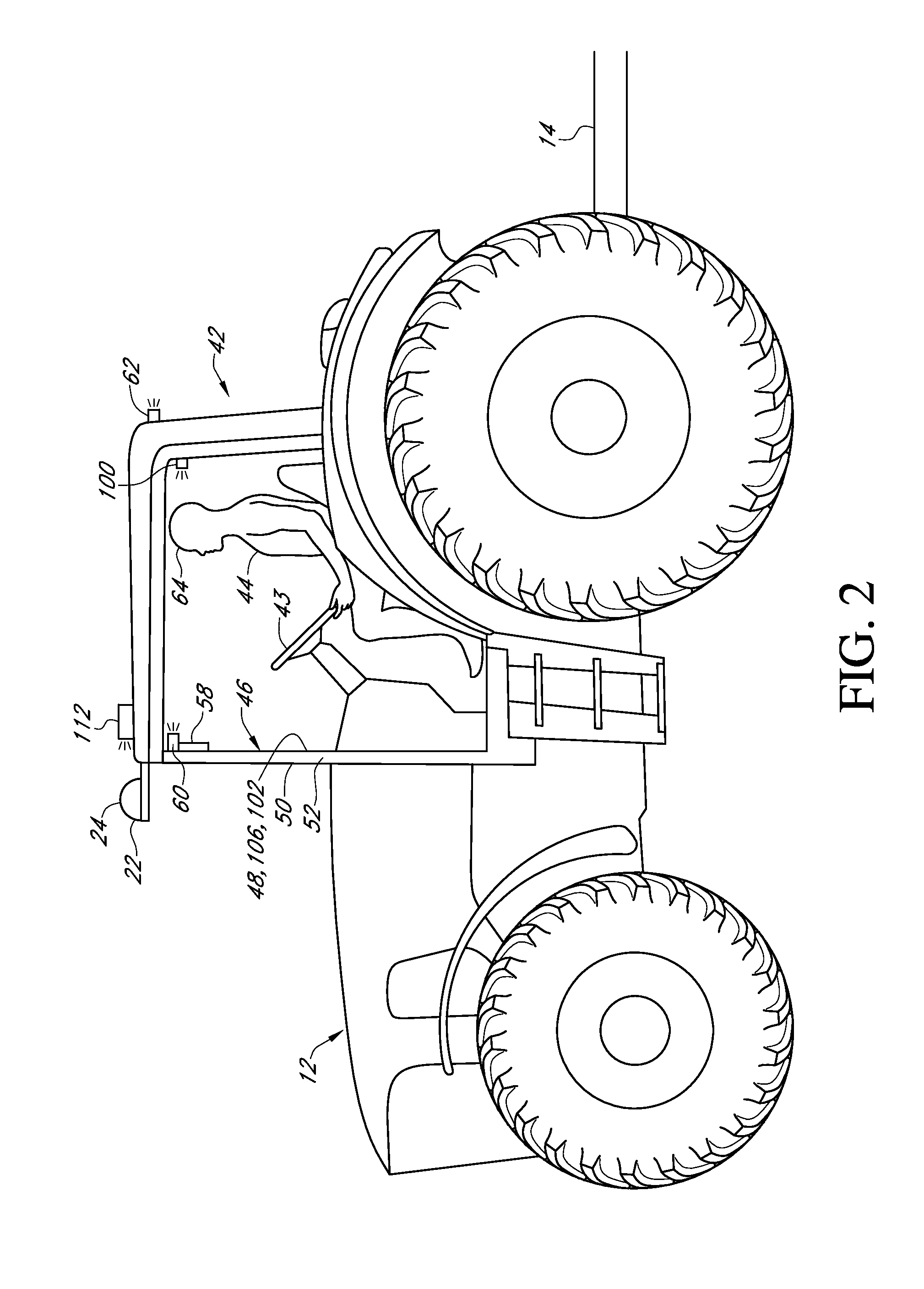
The patent discusses a visual guidance system for a vehicle with an implement. This system allows the operator to clearly see the outermost position of the implement through the windshield of the vehicle. A control system calculates the position of a guidance image and displays it on a display unit. The operator can position the guidance image at the edge of the field or road, which makes it easier to control the vehicle and the implement. Overall, this system provides precise and efficient control for the operator.

Problems solved by technology

Other examples exist wherein the attached implement is a trailer or other object or device connected to the vehicle that has wide berth that provides similar problems to those related to vehicles with other implements.
Namely, as the width of vehicles and / or implements have grown, it has become more difficult for operators to control these vehicles and implements.
This is because the operators have difficulty predicting where the outside edges of the implements will be.
If the operator misjudges where the outside edge of the implement will travel this can cause the implement to strike buildings, fences, terraces, rocks, utility poles, irrigation equipment or the like.
Or alternatively, miscalculation can cause the operator to not cover ground, leaving piles of snow or untilled or unplanted ground, which can cause safety hazards or loss of profits.
Further safety hazards exist when traveling on roads used by pedestrians and other vehicles as a miscalculation can cause injury or an accident.

Method used


Image

  • Visual guidance system
  • Visual guidance system
  • Visual guidance system

Examples


Embodiment Construction

[0042]In the following detailed description, reference is made to the accompanying drawings which form a part hereof, and in which is shown by way of illustration specific embodiments in which the invention may be practiced. These embodiments are described in sufficient detail to enable those skilled in the art to practice the invention, and it is to be understood that other embodiments may be utilized and that mechanical, procedural, and other changes may be made without departing from the spirit and scope of the present inventions. The following detailed description is, therefore, not to be taken in a limiting sense, and the scope of the present invention is defined only by the appended claims, along with the full scope of equivalents to which such claims are entitled.

[0043]As used herein, the terminology such as vertical, horizontal, top, bottom, front, back, end, sides, outer, inner and the like are referenced according to the views presented. It should be understood, however, t...


PUM


Abstract

A visual guidance system is presented. The system includes a vehicle with an implement connected thereto. The vehicle has a windshield through which the operator looks while steering the vehicle. A guidance image is displayed in the operator's sight path and provides a point of reference for the operator that indicates the outer most position of the implement. The position of this guidance image is calculated by a control system and the image is displayed by a display unit. As the operator steers the vehicle, the operator positions the guidance image at the border of the field or road. This allows the user to precisely control the vehicle and the implement in a convenient and efficient manner.

Description

CROSS REFERENCE TO RELATED APPLICATION[0001]This application claims the benefit of U.S. Provisional Application No. 61 / 932,882 filed Jan. 29, 2014.FIELD OF THE INVENTION[0002]This invention relates to a visual guidance system. More specifically, and without limitation, this invention relates to a visual guidance system for vehicles with implements.BACKGROUND OF INVENTION[0003]Implements are often pushed in front of or pulled behind various vehicles in various industries for various reasons. Countless examples of just such an arrangement exist within the agricultural industry and include a tractor pulling a planter, cultivator, sprayer, spreader or similar device. Countless other examples exist within the construction, earth moving and maintenance industries such as a snow plow, bulldozer, grater, paver or similar device which pushes or pulls various blades or other implements to move or remove material. Other examples exist wherein the attached implement is a trailer or other object...

Claims


Application Information

Patent Timeline
Patent Type & Authority Applications(United States)
IPC IPC(8): G01C21/36
CPCG01C21/36G01C21/005G01C21/20G01C21/365B60K35/00B60K35/28B60K2360/166B60K35/23B60W30/00
Inventor EDELEN, BRIAN R.
Owner EDELEN BRIAN R
Learn More