
Optical system for see-through head mounted display

a technology of optical system and display, which is applied in the field of optical system for see-through head mounted display, can solve the problems of user fatigue, increase in the size and weight of the hmd, and increase in the field of view (fov) or the eye box, so as to achieve more efficient business promotion

Inactive Publication Date: 2015-07-30
GREEN OPTICS CO LTD
View PDF7 Cites 17 Cited by
  • Summary
  • Abstract
  • Description
  • Claims
  • Application Information

AI Technical Summary

Benefits of technology

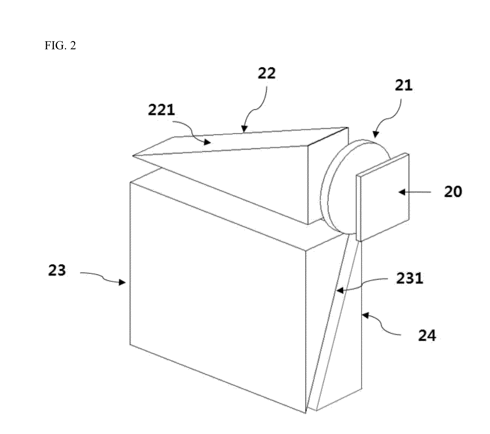
The present invention is a see-through head mounted display (HMD) optical system that allows for clear viewing of both display and external images without significant loss of image quality. The system includes a display device, collimation lens, and two wedge prisms that enlarge the image in both horizontal and vertical directions. The optical system uses an inverse saw-tooth shape third wedge prism to prevent distortion of the external image. The system also has a minimized lens processing cost by applying an enlargement method using a wedge prism. The inclination angles of the two wedge prisms are the same to ensure equal horizontal and vertical enlargment ratios and reduction of image distortion. The invention enables efficient business promotion while walking and allows for large screen viewing.

Problems solved by technology

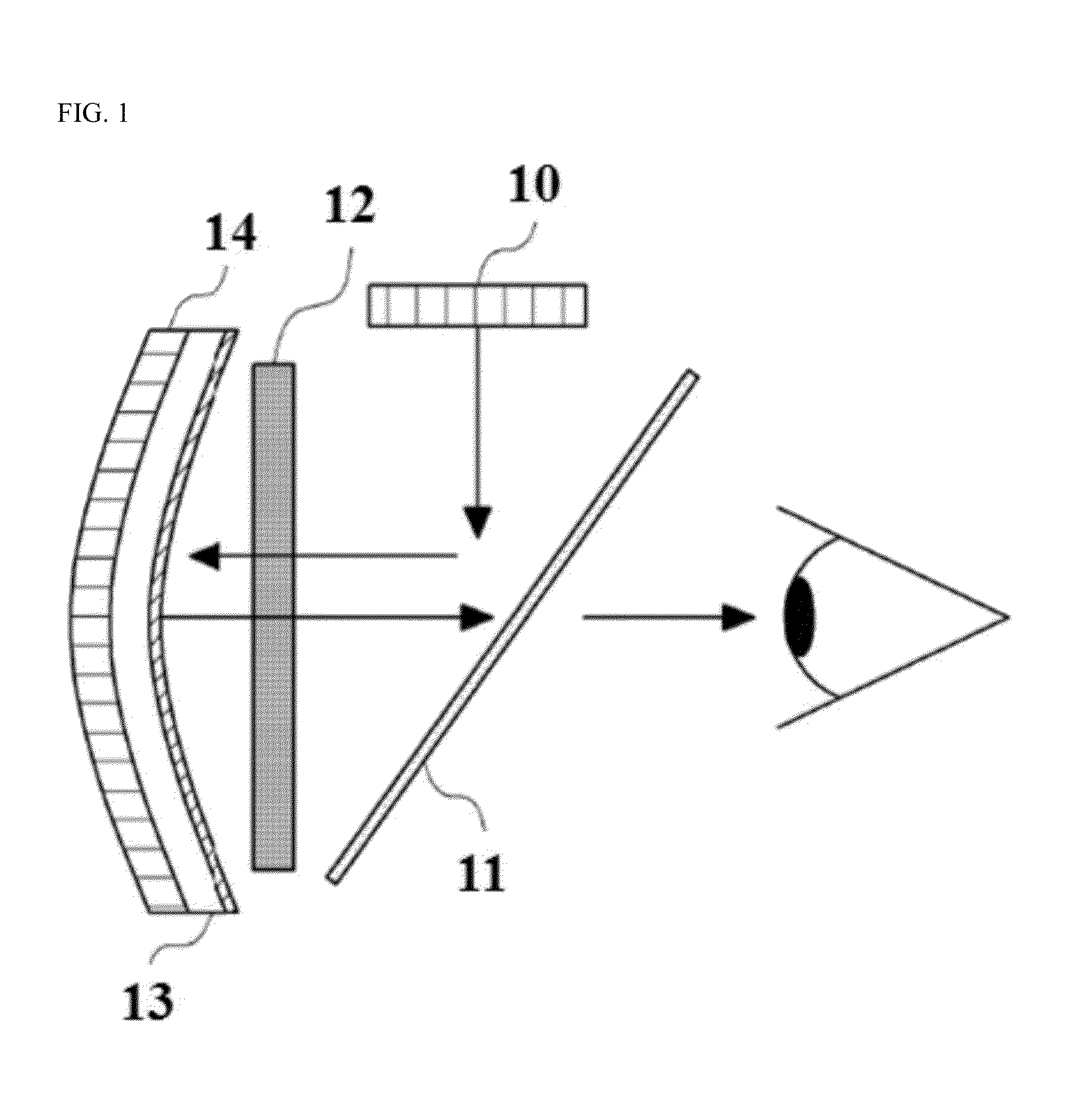
As a result, a natural color of an original image light is difficult to be implemented, and therefore there is a problem that a high-luminance light source has to be separately used in consideration of a magnitude of the amount of light which is lost in order to provide an image with appropriate brightness to user's eyes.
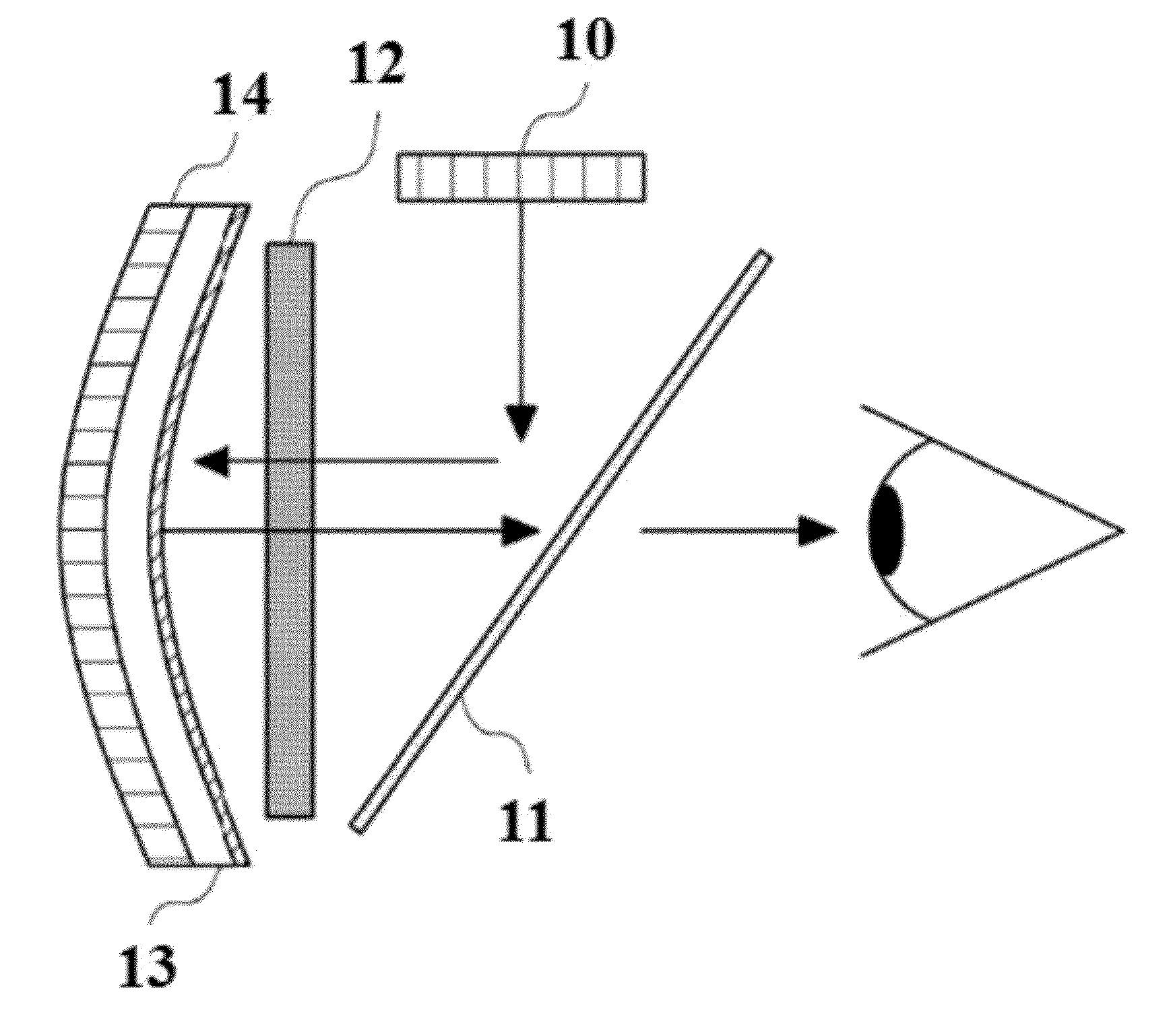
In addition, since the polarized light separator 11 is diagonally positioned in a space in which the image enlarged in the semi-transparent concave reflection mirror 13 reaches both eyes, there is a structural problem in an increase in a field of view (FOV) or an eye box, which is an object of a typical HMD.
Thus, the increase in the FOV and the eye box may cause an increase in the entire size and weight of the HMD.
As a result, when wearing the HMD, a user may easily feel fatigue due to pressurization over the entire face of the user.

Method used


Image

  • Optical system for see-through head mounted display
  • Optical system for see-through head mounted display
  • Optical system for see-through head mounted display

Examples


Embodiment Construction

[0037]Exemplary embodiments of the present invention will be described in detail below with reference to the accompanying drawings. It should be understood that the same configurations throughout the drawings refer to the same signs. Even though particular specific contents are described in the following detailed description, which are intended to help overall understanding. In addition, particular descriptions with regard to related known functions or configurations will be omitted when these are judged to be hinge the gist of the present invention.

[0038]While the present invention is shown and described in connection with exemplary embodiments thereof, it will be apparent to those skilled in the art that various modifications can be made without departing from the spirit and scope of the invention.

[0039]It will be apparent to those skilled in the art that various modifications can be made to the above-described exemplary embodiments of the present invention without departing from ...


PUM


Abstract

Provided is a see-through head mounted display (HMD) optical system which includes a display device, a collimation lens that parallelizes image lights emitted from the display device, a first wedge prism that includes a first enlargement unit for enlarging an image in a horizontal direction, a second wedge prism that includes a second enlargement unit for enlarging the image in a vertical, and a third wedge prism that has an inverse shape of the second wedge prism so as to prevent the image lights which have been reflected in the second wedge prism and enlarged in the vertical direction and an external image which has passed through the second wedge prism and been provided to a user from being distorted.

Description

BACKGROUND[0001]1. Field of the Invention[0002]The present invention relates to an optical system for a see-through head mounted display (HMD), and more particularly, to an optical system for a see-through HMD which may enable information to be easily obtained even during outdoor activities, enable large screen viewing while remarkably reducing a volume and weight thereof, and remarkably reduce manufacturing costs to lower a price of products.[0003]2. Discussion of Related Art[0004]In general, a head mounted display (HMD) apparatus is an image display apparatus in which a virtual large screen is created at a distance by forming a focal point of an image light generated at a position very close to eyes using a precise optical device so that a user can view an enlarged virtual image. As a method of the HMD apparatus, a closed type HMD method to enable only an image light emitted from a display device to be viewed while preventing the surrounding environment from being viewed, and a se...

Claims


Application Information

Patent Timeline
Patent Type & Authority Applications(United States)
IPC IPC(8): G02B27/01
CPCG02B2027/0174G02B27/0172G02B27/0176G02B5/04G02B2027/0118
Inventor CHOI, JANG-HOKIM, DONG-KYUNLEE, SANG-JUN
Owner GREEN OPTICS CO LTD
Learn More