
Cloud Video Surveillance

a video surveillance and cloud technology, applied in the field of video surveillance, can solve problems such as significant problems, nvrs cannot be connected only, and nvrs may experience video data dropouts

Inactive Publication Date: 2015-07-30
RASILIENT SYST INC
View PDF10 Cites 36 Cited by
  • Summary
  • Abstract
  • Description
  • Claims
  • Application Information

AI Technical Summary

Benefits of technology

The disclosure is about a video surveillance system that uses IP cameras and cloud computing resources to capture and store footage. The system is designed so that the IP cameras can access the cloud resources independently through a network. The technical effect of this is that the system can be more flexible and efficient, allowing for better data management and access control.

Problems solved by technology

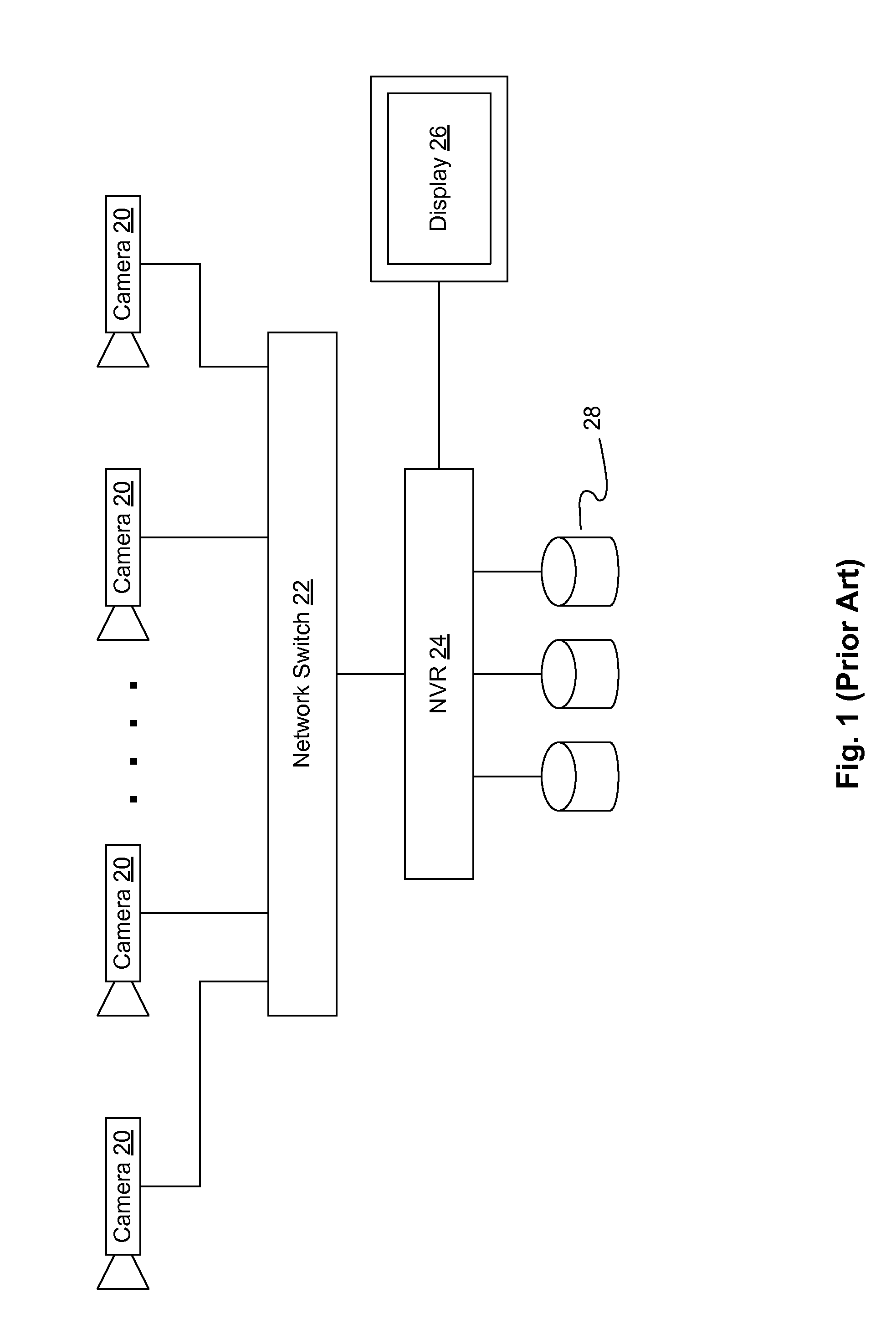
Significant problems occur due to the great number of surveillance cameras connected to the NVRs.
First, each of the NVRs can only be connected to a maximum number of IP cameras.
Second, the resources of the NVRs must be carefully provisioned, or the NVRs may experience dropped video data, increased latency, and other delays caused by overloading.
Any component failures (e.g., camera, switch port, server, storage volume, etc.) will cause problems.
However, such enterprise level surveillance solutions are costly.
Even with enterprise level surveillance solutions, its resources may be temporarily overloaded which would cause video frame drops.
For instance, any software applications (“apps”) for video analytics or otherwise, apps updates, and VMS updates could potentially overload the surveillance system.
Any resource constraints, even temporarily, would cause quality degradation such as dropped video frames.
This is a known industry problem that the NVR 24 would drop frames.
Any new apps, app updates, or VMS updates would potentially cause the NVR 24 to overload and ultimately malfunction.
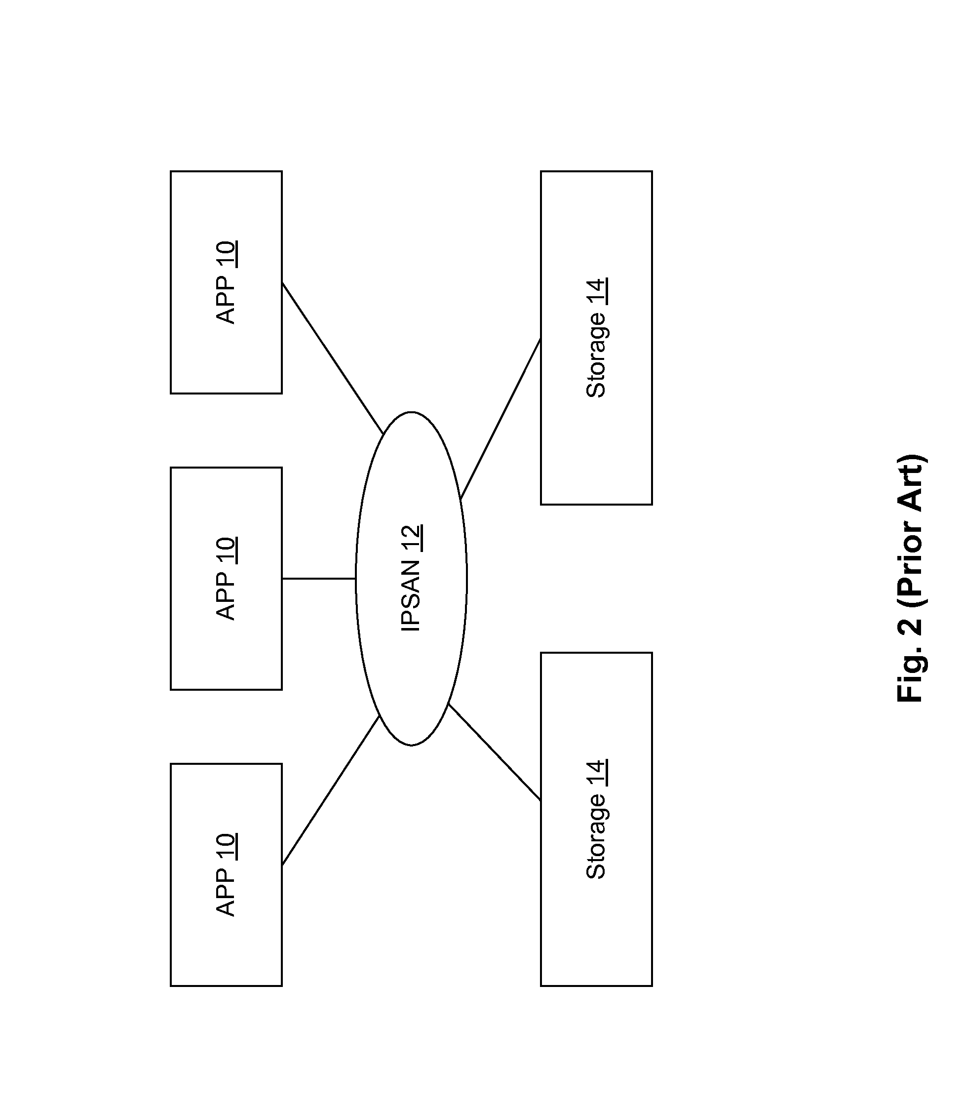
Furthermore, there is no useful way to search or organize the video data in the video storages 14 for easy reference or use by the software applications 10.
Currently, surveillance systems have no way to extract useful information from video data.
Scanning the recorded video from the outside world is almost impossible since the recorded video is difficult to access and since each NVR is an island in itself.
If real time analytics are not operational or not performed correctly, then there is no way to scan for specific objects without having to rescan all the recorded data.

Method used


Image

  • Cloud Video Surveillance
  • Cloud Video Surveillance
  • Cloud Video Surveillance

Examples


Embodiment Construction

[0026]In the following detailed description of the embodiments, reference is made to the accompanying drawings, which form a part hereof, and in which is shown by way of illustration of specific embodiments in which the disclosure may be practiced.

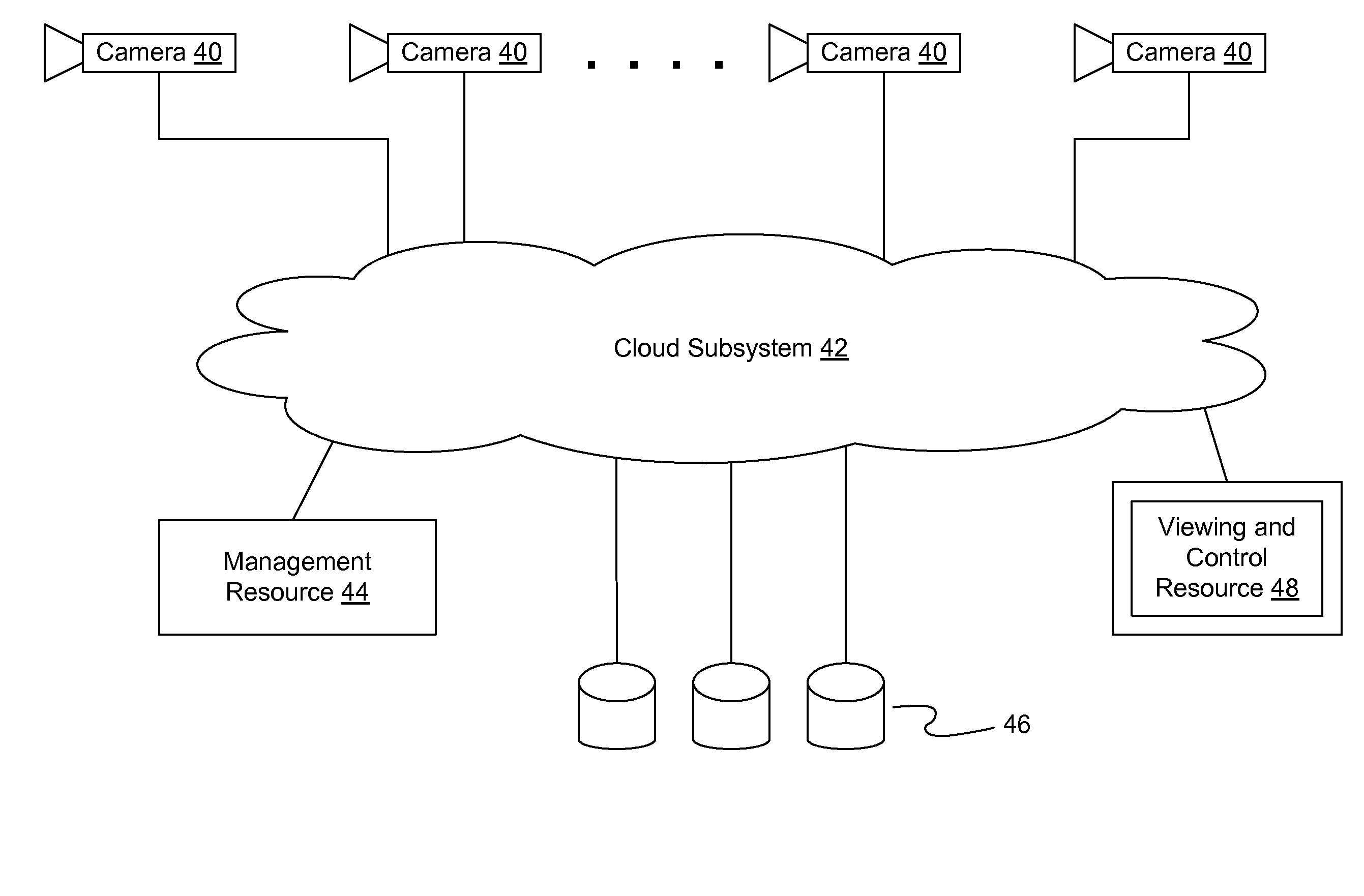
[0027]Cloud resources are supported by data centers with a concentration of information technology (“IT”) resources for computing, storage, and interconnection. An important cloud concept is the assumption that an interconnection something can fail without losing access to the IT resources and services. This is due to the fact that a cloud subsystem is extremely scalable. This assumption leads to various cloud technologies, which can remove end-to-end provisioning requirements. In other words, data does not need to travel through a specific path, specific switch port, specific server, or to a specific volume of a storage device.

[0028]In a cloud subsystem, the data can go through any path and be stored in multiple places. Similarly, resourc...


PUM


Abstract

A video surveillance system comprises internet protocol (“IP”) cameras; a network; and cloud computing resources having a management resource, a video storage resource, and a viewing and control resource. The IP cameras and cloud computing resources are connected via the network. The IP cameras independently access each of the cloud computing resources. An application software of a device connected to the network identifies one or more objects of interest from the video data of the IP cameras for extraction.

Description

CROSS REFERENCES[0001]This application claims priority from a provisional patent application entitled “Methods to Provide Cloud Video Surveillance” filed on Dec. 4, 2013 and having an Application No. 61 / 911,808 and from a provisional patent application entitled “Methods to Extract Intelligence from Surveillance Video” filed on Dec. 4, 2013 and having an Application No. 61 / 911,817. Said applications are incorporated herein by reference.FIELD OF INVENTION[0002]The disclosure relates to video surveillance, and, more particularly, to methods and systems for video surveillance using cloud networking resources.BACKGROUND[0003]Video surveillance is transitioning from analog cameras to internet protocol (“IP”) cameras. For instance in 2013, 50% of North American deployments used IP cameras. The percentage of IP camera deployments is lower worldwide, but is quickly accelerating.[0004]A typical analog video surveillance system connects analog cameras from various locations to a centralized st...

Claims


Application Information

Patent Timeline
IPC IPC(8): H04N7/18G08B13/196
CPCH04N7/181G08B13/19656G08B13/19645G08B13/196
Inventor CHANG, YEE-HSIANG SEAN
Owner RASILIENT SYST INC
Learn More