Reaction force generator

Active Publication Date: 2015-08-06
YAMAHA CORP
View PDF8 Cites 10 Cited by
  • Summary
  • Abstract
  • Description
  • Claims
  • Application Information

AI Technical Summary

Benefits of technology

[0009]In the reaction force generator constructed as described above, a rate of deformation of the dome member is made generally uniform in the entire dome member when the dome member is pressed by the operating member, preventing local deformatio

Problems solved by technology

As a result, when depressing the key with a finger, the ope

Method used


Image

  • Reaction force generator
  • Reaction force generator
  • Reaction force generator

Examples


first embodiment

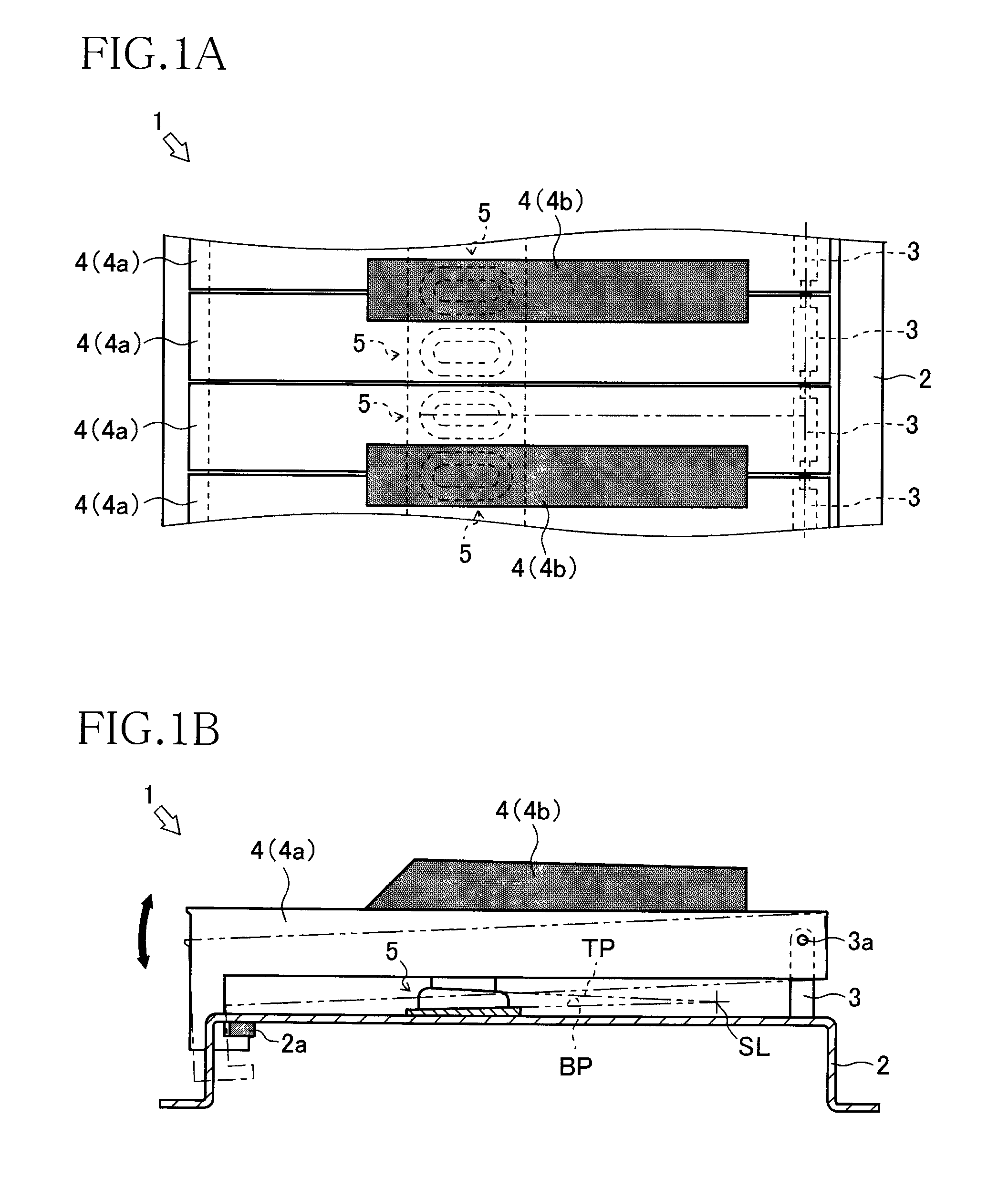
[0022]There will be explained a keyboard device 1 in one embodiment of the present invention with reference to FIG. 1. In the present embodiment, the keyboard device 1 is a keyboard device of an electronic keyboard instrument.

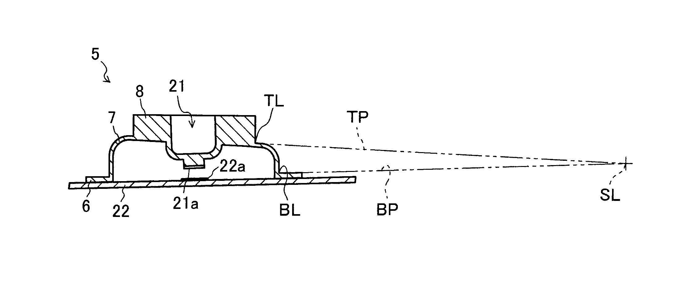
[0023]The keyboard device 1 includes a frame (as one example of a supporter) 2, an upper-limit stopper 2a, a key fulcrum members 3, a plurality of keys 4 (including white keys 4a and black keys 4b), and a plurality of reaction force generators 5. The keyboard device 1 is disposed on the frame 2 as the supporter such that the keys 4 (the white keys 4a and the black keys 4b) are adjacent to each other. Each of the keys 4 is provided such that one end of the key 4 is pivotably supported by a corresponding one of the key fulcrum members 3 provided on the frame 2, via a pivot shaft 3a as a pivot fulcrum, and the other end of the key 4 is held in contact with the upper-limit stopper 2a provided on the frame 2. Also, the reaction force generators 5 and a plurality of ...

second embodiment

[0040]There will be next explained, with reference to FIGS. 6A-6C, a reaction force generator 9 according to a second embodiment of the present invention. It is noted that the same reference numerals as used in the first embodiment are used to designate the corresponding elements of this second embodiment, and an explanation of which is dispensed with. The reaction force generator 9 generates the reaction force against the operation on the key 4 as the operating member and includes the base member 6, a dome member 10, and a top member 11.

[0041]The dome member 10 is shaped like a hollow dome expanded and protruding from the other-side surface of the base member 6 toward the key 4 of the keyboard device 1. Specifically, the dome member 10 includes a side wall 10a having an oval shape (or an elongated hole shape) in which a straight line connects between a pair of arcs having different diameters and spaced apart from each other in plan view when viewed from the other side of the base m...

third embodiment

[0047]There will be next explained, with reference to FIG. 7, a reaction force generator 12 according to a third embodiment of the present invention. The reaction force generator 12 according to the present embodiment has the same shape as that in the first embodiment and the second embodiment in top view (i.e., in plan view when viewed from the other side of the base member 6). In side view, as illustrated in FIG. 7, the reaction force generator 12 generates the reaction force against the operation on the key 4 as the operating member and includes the base member 6, a dome member 13, and the top member 8.

[0048]The dome member 13 is shaped like a hollow dome expanded and protruding from the other-side surface of the base member 6 toward the key 4 of the keyboard device 1. Specifically, the dome member 13 protrudes from the base member 6 such that a portion of a side wall 13a which is located on an opposite side of the top member 8 from the pivot shaft 3a, i.e., one of opposite porti...


PUM

PropertyMeasurementUnit
Thicknessaaaaaaaaaa
Forceaaaaaaaaaa
Lengthaaaaaaaaaa

Abstract

A reaction force generator includes: a base member mounted on a supporter supporting an operating member pivotably; a dome member protruding from the base member; and a top member provided on a protruding-side end of the dome member to be pressed by the operating member toward the base member. The dome member is deformed to produce a reaction force when the top member is pressed by the operating member. A basal-end-side plane and a distal-end-side plane intersect each other at a position located on one of opposite sides of the dome member which is nearer to a pivot fulcrum of the operating member. The basal-end-side plane includes a line of intersection between the base member and the dome member adjacent to each other. The distal-end-side plane includes a line of intersection between the dome member and the top member adjacent to each other.

Description

CROSS REFERENCE TO RELATED APPLICATION[0001]The present application claims priority from Japanese Patent Application No. 2014-021719, which was filed on Feb. 6, 2014, the disclosure of which is herein incorporated by reference in its entirety.BACKGROUND[0002]1. Technical Field[0003]The present invention relates to a reaction force generator and more particularly to a reaction force generator configured to generate a reaction force when pressed by an operating member.[0004]2. Description of the Related Art[0005]There is conventionally known a reaction force generator configured to generate a reaction force against an operating member depressed and pivoted by an operator. The reaction force generator includes a protruding dome member made of an elastic material such as rubber. When the reaction force generator is pressed by the operating member, the dome member is deformed, causing the reaction force generator to generate a reaction force against the operating member due to the deform...

Claims


Application Information

Patent Timeline
IPC IPC(8): G05G5/03H01H1/14
CPCG05G5/03H01H13/702H01H1/14H01H13/705H01H13/85H01H2215/006H01H2215/026H01H2221/016
Inventor HARIMOTO, HIROSHIOSUGA, ICHIRO
Owner YAMAHA CORP
Why Eureka
Try Eureka