
Multichannel audio system having audio channel compensation

a multi-channel audio and compensation technology, applied in the field of multi-channel audio systems, can solve the problems of reducing reducing the psychoacoustic perception of the listener in the listening position, and affecting the enjoyment of listening experien

Active Publication Date: 2015-08-06
HARMAN INT IND INC
View PDF4 Cites 4 Cited by
  • Summary
  • Abstract
  • Description
  • Claims
  • Application Information

AI Technical Summary

Benefits of technology

This patent describes a technical feature of a multichannel compensating audio system. One interesting thing it does is equalizing the loudness of different sounds emitted from multiple speakers in a listening space. This results in a more consistent and balanced listening experience for different listeners. Additionally, the technology allows for the "movement" of the listener's perceived location in relation to the sound source, making the listening experience more immersive.

Problems solved by technology

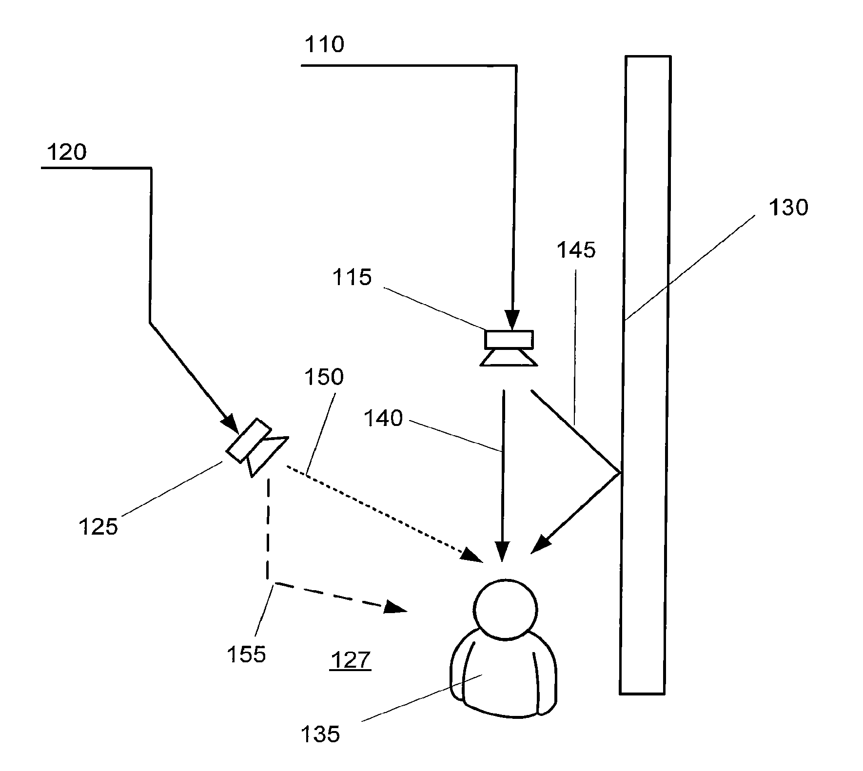
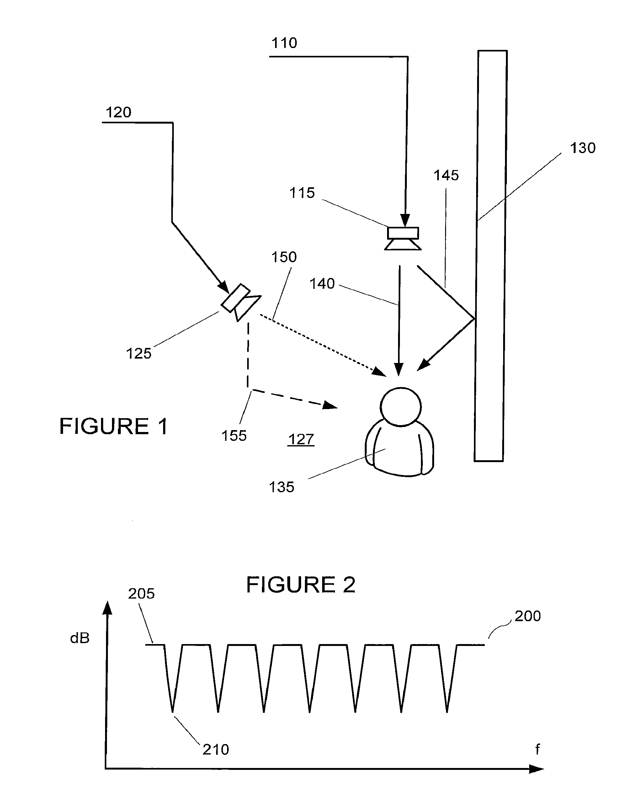
A listener in such an environment is presented with both the original sound and a delayed version of the sound, which results in constructive and destructive interference.
Each listener in the cabin receives both direct and reflected sound associated with each channel, resulting in deviations such as complex comb filtering interactions that reduce enjoyment of the listening experience.
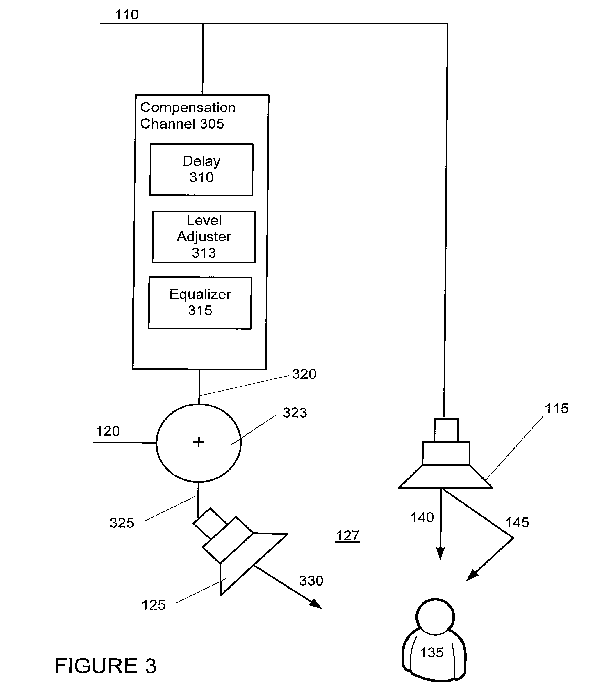
However, due to the multichannel compensating audio system, the listener in the listening position may not psychoacoustically perceive a change in the location of origin of the first audio signal.

Method used


Image

  • Multichannel audio system having audio channel compensation
  • Multichannel audio system having audio channel compensation
  • Multichannel audio system having audio channel compensation

Examples


Embodiment Construction

[0023]Deviations in a target frequency response at one or more listening positions within a listening space, such as passenger locations in a vehicle, may be at least partially addressed with selective frequency equalization of the audio signal. For example, a comb filtering effect associated with a channel may be at least partially addressed by providing equalization to the affected channel. Such equalization may involve providing frequency boosts and / or frequency reductions directly to the channel to correct for the dips and peaks representative of deviations in the target frequency response. Although deviations in the target frequency response for a given channel may depend on the location of a listener within the listening space or listening environment, a general frequency equalization setting may be provided on the channel based on the common areas in which the listener is positioned within the listening space or listening environment.

[0024]Application of equalization directly...


PUM


Abstract

A multichannel compensating audio system includes first and second compensation channels to psychoacoustically minimize deviations in a target response, to psychoacoustically move the physical position of a speaker and / or to psychoacoustically provide a substantially equal magnitude of sound from a plurality of speakers in a plurality of different listening positions. The first compensation channel may include a series connected delay circuit, a level adjuster circuit and a frequency equalizer circuit that generates a first compensated audio signal from a first audio signal. The second compensation channel may include a series connected delay circuit, a level adjuster circuit and a frequency equalizer circuit that generates a second compensated audio signal from a second audio signal. A first summing circuit is configured to receive at least the first audio signal and the second compensated audio signal and generate a first output signal for provision to a first speaker. A second summing circuit is configured to receive the second audio signal and the first compensated audio signal and generate a second output signal for provision to a second speaker. The first and second output signals may be output by the first and second speakers into a listening space and are acoustically perceived by a listener.

Description

PRIORITY CLAIM[0001]This application claims the benefit of priority from U.S. Provisional Application No. 61 / 248,760, filed Oct. 5, 2009, which is incorporated by reference.BACKGROUND OF THE INVENTION[0002]1. Technical Field[0003]The present invention relates to multichannel audio systems and, more particularly, to an audio channel compensation system for a multichannel audio system.[0004]2. Related Art[0005]The perception of sound provided by an audio system in an environment may be degraded by reflective surfaces in that environment. A listener in such an environment is presented with both the original sound and a delayed version of the sound, which results in constructive and destructive interference. This type of interference can produce deviations, such as a comb filtering effect, in a target frequency response. The frequency response of a comb filter includes a series of regularly-spaced peaks and troughs, giving the appearance of a comb. The listener therefore receives a soun...

Claims


Application Information

Patent Timeline
Patent Type & Authority Applications(United States)
IPC IPC(8): H04R5/02
CPCH04R2499/13H04S1/002H04R5/02H04S7/305H04S2400/11H04S3/002H04S1/00H04S3/00H04S7/00
Inventor SOULODRE, GEORGE ARTHUR JOSEPH
Owner HARMAN INT IND INC
Learn More