
Adaptive Traffic Dynamics Prediction

a traffic dynamics and prediction technology, applied in the detection of traffic movement, traffic control systems, instruments, etc., can solve the problems of inability to adapt to the changes in traffic dynamics, varies geospatially and can be sparse, and the penetration of probe data is difficul

Active Publication Date: 2015-08-13
HERE GLOBAL BV
View PDF8 Cites 53 Cited by
  • Summary
  • Abstract
  • Description
  • Claims
  • Application Information

AI Technical Summary

Benefits of technology

The patent text describes a system for predicting traffic speed and providing users with accurate information about the expected travel time to their destination. The system uses historical traffic pattern data, which is a composite of speed data measured over a period of time, to estimate the typical speed of a road at a given time and under specific conditions such as time of day, day of week, or scheduled events. This data is then used to predict the expected travel time for short-term future trips, which can be useful for users to make decisions like when to start a trip or when to arrive at a destination. The system can also use real-time RT data, which provides the current speed of the road measured or modeled at a particular time, but may not be retained in its unprocessed form. The technical effect of the patent text is to provide a system for accurately predicting traffic speed and travel time to destinations, which can be useful for users, governmental or regulatory agencies, news organizations, or other service providers.

Problems solved by technology

However, the penetration of probe data, i.e. the number of available and / or reliable data sources for a given road at a given time, varies geospatially and can be sparse.
As such, these rudimentary models cannot accommodate changes in dynamics that are associated with common changes in traffic dynamics, such as holidays.
Furthermore, these low level models for each segment operate independently and consequently cannot predict dynamics that are highly unlikely.
In practice, this may lead to surface streets being combined whereas highway links tend to remain separately treated however this is not guaranteed for a given network of roads.
Additionally, the illustrations are merely representational and may not be drawn to scale.

Method used


Image

  • Adaptive Traffic Dynamics Prediction
  • Adaptive Traffic Dynamics Prediction
  • Adaptive Traffic Dynamics Prediction

Examples


Embodiment Construction

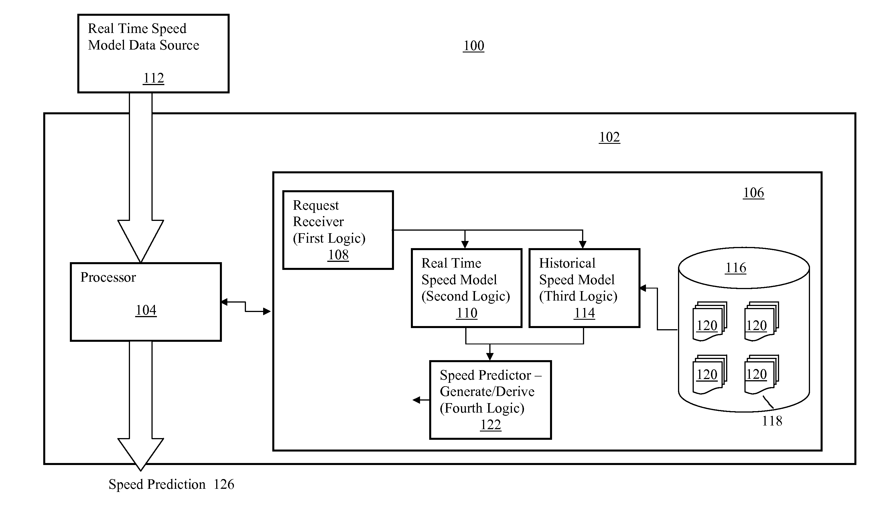
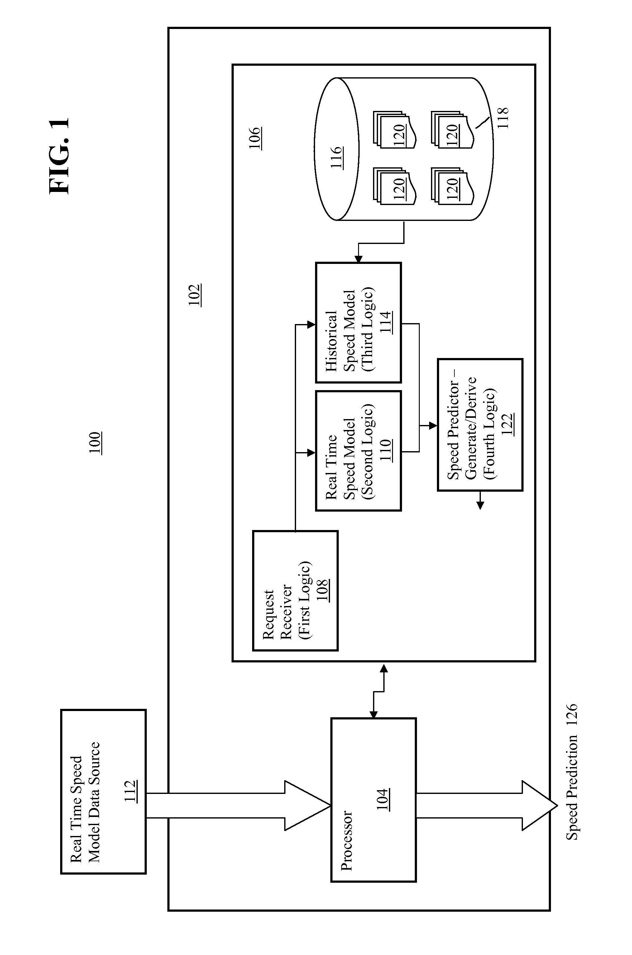
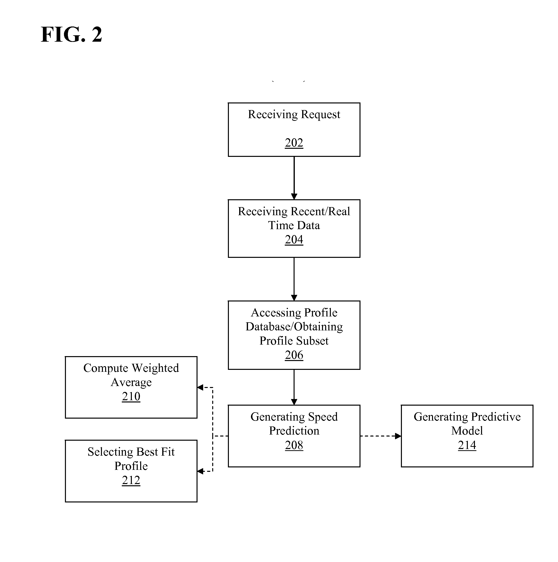
[0017]The disclosed embodiments relate to prediction of traffic dynamics. A descriptive model is provided that uses historical probe data to create “tidal-like” patterns for the usual dynamics on the road network and creates a framework for taking a future time, e.g. in terms of month, day, time, and suggesting a typical speed for the specified road network link at that specific time. With this model, better predictions for estimated time of arrival will be derived. As opposed to blindly extrapolating from a static model, the disclosed embodiments dynamically adapt to current conditions using real time data to adapt, based on current conditions, the model from which a predicted speed may be determined.

[0018]In one embodiment, historical speed profiles are built for the road network by clustering historical patterns into, for example, 2 day or 7 day models. These models may be built using k-means clustering, a method of vector quantization which aims to partition n observations into ...


PUM


Abstract

The disclosed embodiments relate to prediction of traffic dynamics. A descriptive model is provided that uses historical probe data to create “tidal-like” patterns for the usual dynamics on the road network and creates a framework for taking a future time, e.g. in terms of month, day, time, and suggesting a typical speed for the specified road network link at that specific time. With this model, better predictions for estimated time of arrival will be derived. As opposed to blindly extrapolating from a static model, the disclosed embodiments dynamically adapt to current conditions using real time data to adapt, based on current conditions, the model from which a predicted speed may be determined.

Description

REFERENCE TO APPENDICES[0001]The Appendices placed at the end of the specification and forming a part hereof show exemplary implementation details in accordance with the present teachings. These Appendices include:[0002]Appendix A: Probe and Flow Model Integration: Probe Data Clustering Workflow;[0003]Appendix B: Probe and Flow Model Integration: Descriptive Model;[0004]Appendix C: Probe Data Clustering: Long-term Predictive Model;[0005]Appendix D: Probe Data Clustering: Short-term Model and Real-time Scoring Engine;[0006]Appendix E: A Method to Prepare Raw Probe Data for Traffic Analysis.BACKGROUND[0007]Navigation systems are available that provide end users with various navigation-related functions and features. For example, some navigation systems are able to determine an optimum route to travel along a road network from an origin location to a destination location in a geographic region. Using input from the end user, the navigation system can examine various potential routes be...

Claims


Application Information

Patent Timeline
Patent Type & Authority Applications(United States)
IPC IPC(8): G08G1/01
CPCG08G1/0141G08G1/0129G08G1/0112G08G1/0116G08G1/012
Inventor MACFARLANE, JANEGROSSMAN, ROBERTBENNETT, COLLINPIVARSKI, JAMES
Owner HERE GLOBAL BV
Learn More