
Rotor with magnet pattern

a magnet pattern and rotor technology, applied in the direction of magnetic circuit rotating parts, dynamo-electric machines, magnetic circuit shape/form/construction, etc., can solve the problems of difficult and expensive manufacturing of known designs, and achieve the effect of improving optimization, difficult and expensive manufacturing

Inactive Publication Date: 2015-08-13
ALBUS TECH
View PDF20 Cites 43 Cited by
  • Summary
  • Abstract
  • Description
  • Claims
  • Application Information

AI Technical Summary

Benefits of technology

The invention is about a new design for an electrical machine that uses a planar unit as its rotor. The design helps to optimize the use of magnet material in the rotor, and may be simpler and less expensive to manufacture compared to some previous designs. Overall, the technical effect of the invention is to improve the efficiency and performance of electrical machines.

Problems solved by technology

The designs may also be advantageous in that they may be more simple than some prior art designs, since some embodiments require only two types of magnetic pieces whereas some comparably efficient prior art designs require manufacture and assembly of a larger number of types of magnetic pieces, which may make those known designs more difficult and expensive to manufacture.

Method used


Image

  • Rotor with magnet pattern
  • Rotor with magnet pattern
  • Rotor with magnet pattern

Examples


Embodiment Construction

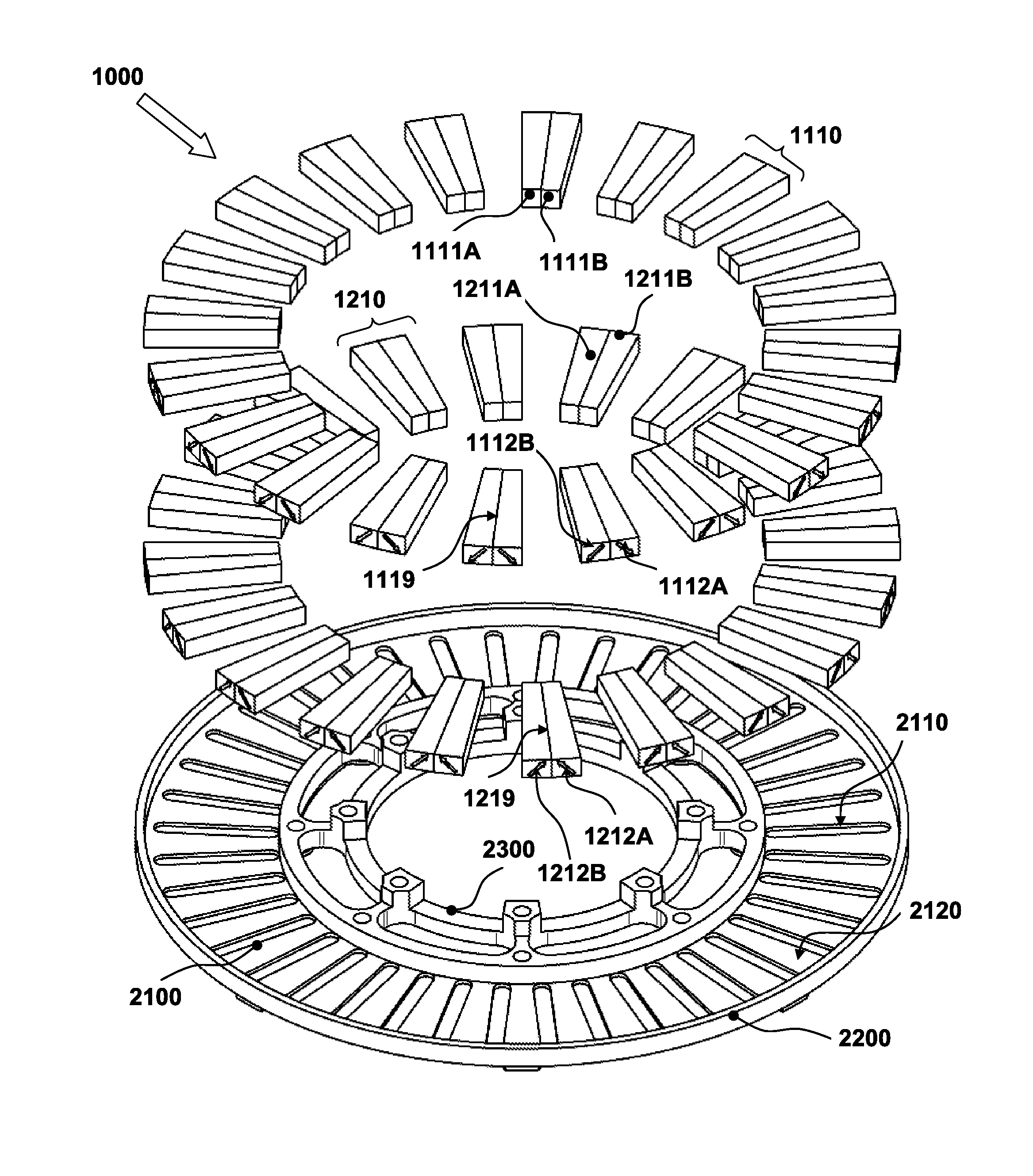
[0082]The present invention, in some embodiments thereof, relates to rotors for electric machines such as an electric motors and / or generators, and, more particularly, but not exclusively, to patterns for magnetic elements of planar rotors for axial air-gap electric machines.

[0083]As used throughout the present disclosure and in the claims below, the terms “machine” and “electrical machine” are to be understood to include both electric motors and electric generators.

Previously Known Designs

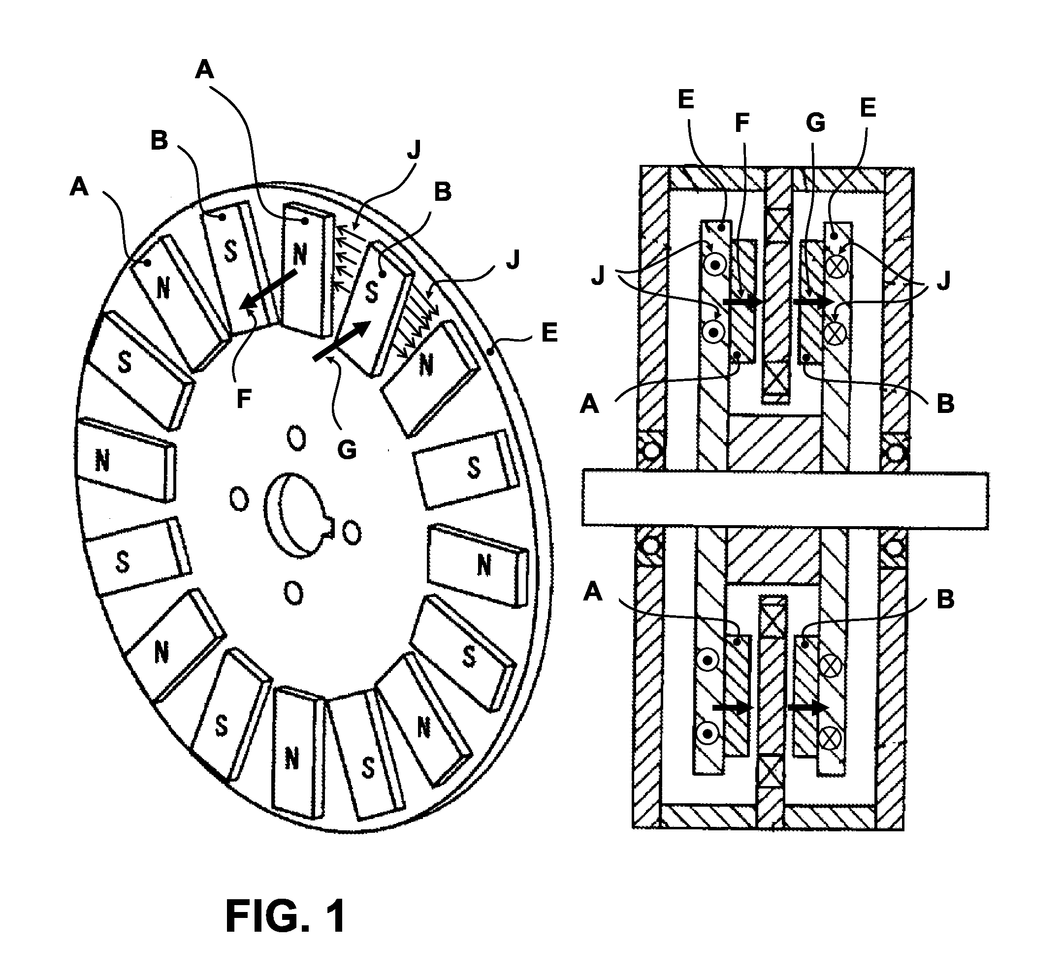
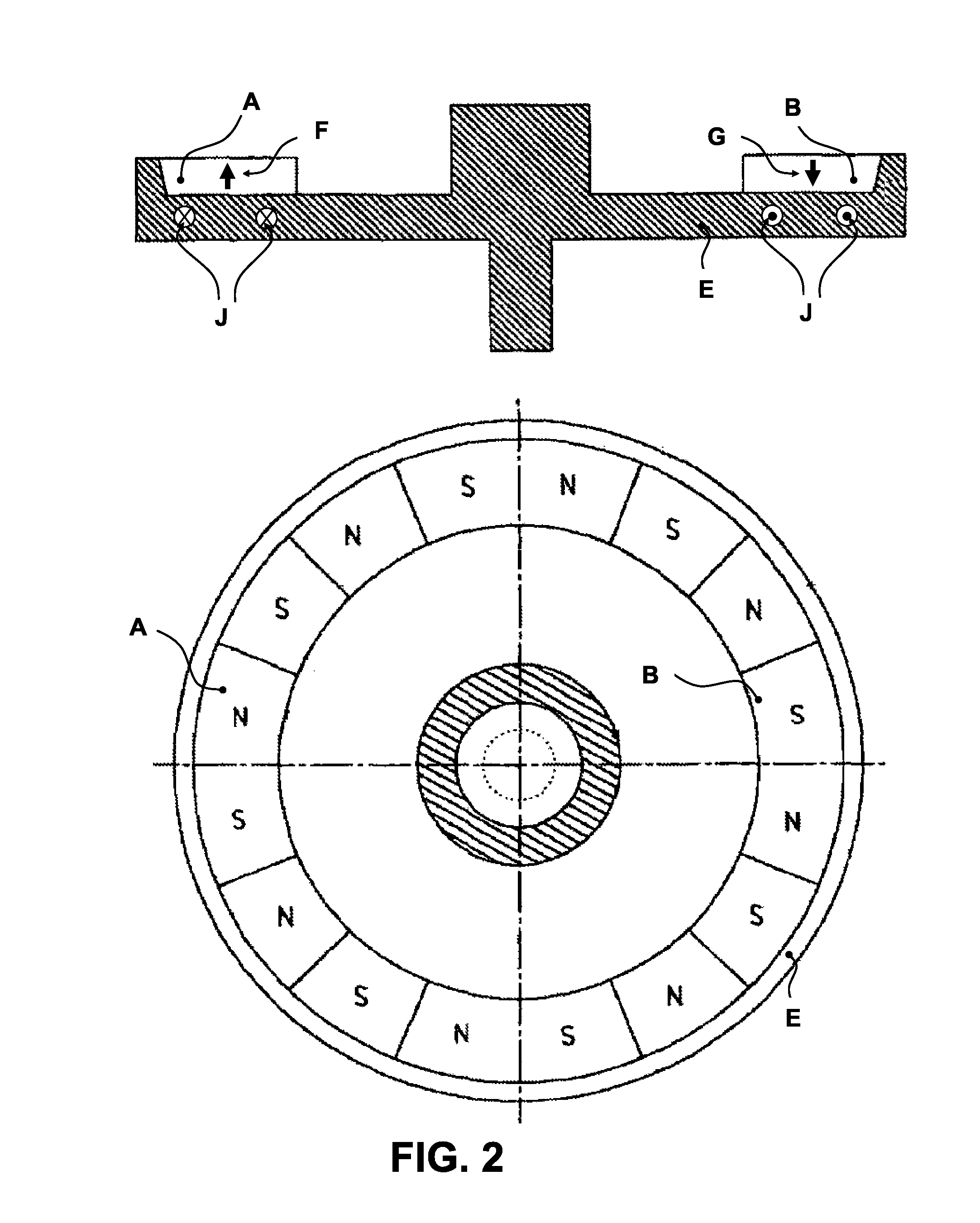
[0084]For purposes of better understanding some embodiments of the present invention, as illustrated in FIGS. 8-19 of the drawings, reference is first made to the construction and operation of several known designs for rotors, as illustrated in FIGS. 1-7.

[0085]Attention is first drawn to FIGS. 1 and 2, which show heteropolar magnet systems of axial flux rotors, according to methods of prior art. FIG. 1 is adapted from US patent application 2010 / 0253173 A1 of Koji Miyata et al. FIG. 2 is adapted fr...


PUM


Abstract

Planar rotor designs for axial air-gap electric machines are presented. Some embodiments comprise rotors each of whose magnetic poles comprise a pair of permanent magnets each magnetized in an orientation of about 45° to the direction of the rotor axis. In some embodiments, axial components of the magnetization of each pair of magnets are co-directional, and tangential components of the magnetization of each pair of magnets are opposite.

Description

RELATED APPLICATIONS[0001]This application claims the priority and benefit under 35 USC 119(e) of US Provisional Patent Applications 61 / 773,295 filed 6 Mar. 2013 and 61 / 693,375 filed 27 Aug. 2012, the disclosures of which are incorporated herein by reference.FIELD AND BACKGROUND OF THE INVENTION[0002]The present invention, in some embodiments thereof, relates to a rotor for an electric machine such as an electric motor or generator, and, more particularly, but not exclusively, to patterns for magnetic elements of a planar rotor for an axial air-gap electric machine.[0003]As an aid to understanding the present invention, several examples of known designs for planar rotors of axial air-gap machines are presented, for purposes of comparison, in the accompanying figures, and are discussed herein. As will be seen in that discussion, some of these designs presented may be relatively inefficient in the use of space available for a planar rotor, as compared to some embodiments of the presen...

Claims


Application Information

Patent Timeline
IPC IPC(8): H02K16/02H02K1/27
CPCH02K1/2793H02K16/02H02K1/32H02K21/24H02K1/2798H02K3/28
Inventor SROMIN, ALEXANDER
Owner ALBUS TECH
Learn More