Selectively Bendable Remote Gripping Tool

a remote access gripping and selective bend technology, applied in the field of selectively bendable remote access gripping tools, can solve the problems of complex construction of tools, and achieve the effect of reducing invasiveness and potential trauma, and less invasiv

Active Publication Date: 2015-08-20
KOVARIK CARTER J +1
View PDF5 Cites 17 Cited by
  • Summary
  • Abstract
  • Description
  • Claims
  • Application Information

AI Technical Summary

Benefits of technology

[0045]In certain embodiments, the surgical device set forth here can be employed to treat pulmonary embolization by the appropriate placement of a thrombus filter in the vascular system of a patient's body. Placement of the filter may be accomplished by intravenous insertion of a thrombus filter in a patient's vascular system, which is less invasive and requires only a local anesthetic. Once placed inside a blood vessel, a thrombus filter acts to catch and hold blood clots. The flow of blood around the captured clots allows the body's lysing process to dissolve the clots.
[0046]Some medical instruments can reduce the invasiveness and potenti...

Problems solved by technology

Such tools, however, are often complicated in terms of construction, often employing rails and jointed connecti...

Method used


Image

  • Selectively Bendable Remote Gripping Tool
  • Selectively Bendable Remote Gripping Tool
  • Selectively Bendable Remote Gripping Tool

Examples


Embodiment Construction

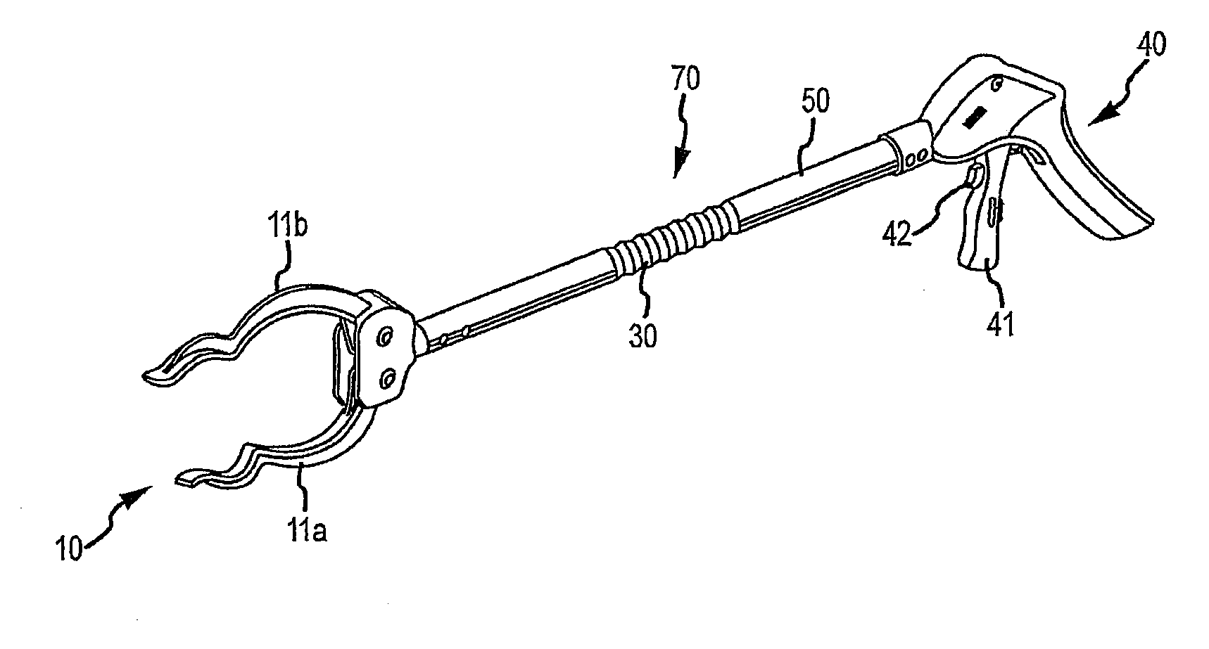
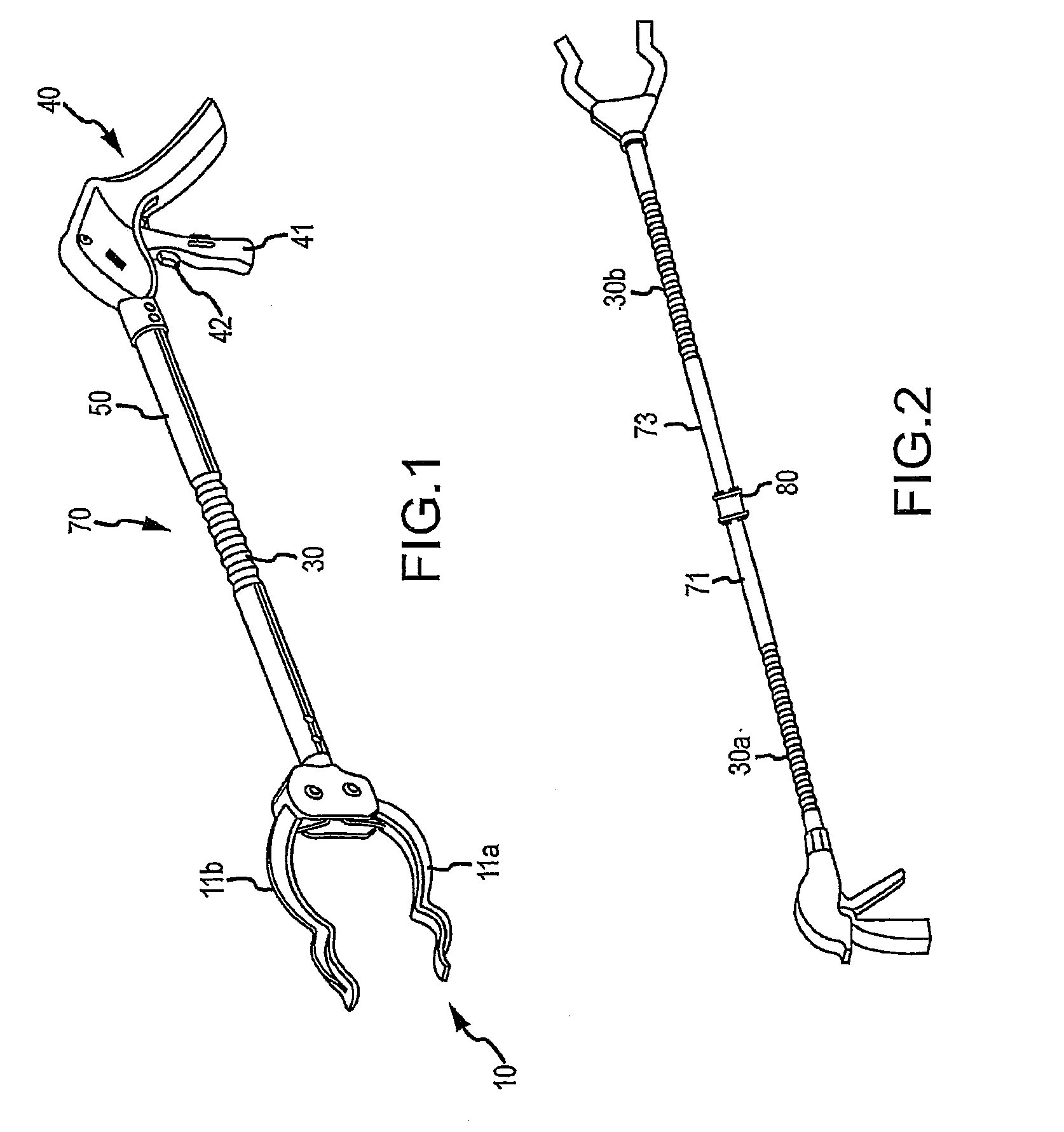
[0077]It will be understood that the disclosed embodiments are merely exemplary of the invention that may be embodied in various and alternative forms. The figures are not necessarily to scale, some features may be exaggerated or minimized to show details of particular components. Therefore, specific structural and functional details disclosed herein are not to be interpreted as limiting, but merely as a representative basis for teaching one skilled in the art to variously employ the present invention. For the following description, the actuatable tool head assembly is described as a gripper having a jaw assembly 11. It is understood, however, that any type of actuatable tool head assembly may be used.

[0078]As disclosed in the figures, various embodiments of the present invention generally comprise a hand-held gripping device having a jaw portion (indicated generally at 10) comprising a pair of jaws 11a, 11b and a handle portion (indicated generally at 40) spaced apart by a selectiv...


PUM


Abstract

A hand-held gripping device that allows one of a surgeon, a dentist, and an orthodontist to reach interior portions of a person's anatomy, includes a gripping portion having a pair of jaws movable relative to each other between fully clamped and fully opened positions thereof, a handle portion spaced apart from the jaw portion by a bendable central portion that has a hollow, bendable corrugated with at least one cord extending therethrough.

Description

RELATED APPLICATIONS[0001]This application is a continuation-in-part application of U.S. patent application Ser. No. 14 / 539,021, filed on Nov. 12, 2014, which is a continuation of U.S. patent application Ser. No. 14 / 535,539, filed on Nov. 7, 2014, which is a continuation-in-part of U.S. patent application Ser. No. 14 / 290,207, filed on May 29, 2014, which is a continuation-in-part of U.S. patent application Ser No. 14 / 163,521 filed on Jan. 24, 2014 (now U.S. Pat. No. 8,833,817, issued Sep. 16, 2014), which is a continuation-in-part application of U.S. patent application Ser. No. 14 / 078,830 filed on Nov. 13, 2013 (now U.S. Pat. No. 8,807,615, issued Aug. 19, 2014), which is a continuation-in-part of U.S. patent application Ser. No. 13 / 771,813 filed on Feb. 20, 2013 (now U.S. Pat. No. 8,585,114, issued Nov. 19, 2013), and claims priority from U.S. Provisional Patent Application Ser. No. 61 / 601,789, filed on Feb. 22, 2012. This application also seeks priority from U.S. patent applicatio...

Claims


Application Information

Patent Timeline
IPC IPC(8): A61B17/22A61B17/3201A61B1/06A61C3/14A61C1/18A61B1/24A61B1/04A61C3/02A61B17/221A61C1/08
CPCA61B17/22031A61B17/221A61B17/3201A61B1/06A61C1/088A61C1/185A61B2017/2212A61B1/04A61C3/02A61C3/14A61B2017/00367A61B2017/22034A61B2017/22035A61B1/24A01K77/00B25J1/02B26B17/02E01H1/1206A61B2017/2215E01H2001/1293A01G3/025A61B2017/00991A61B2017/2905A61B1/045A61B1/0655
Inventor KOVARIK, CARTER J.KOVARIK, JOSEPH E.
Owner KOVARIK CARTER J
Why Eureka
Try Eureka