
Movable horizontal tail for catapult toy glider

Inactive Publication Date: 2015-08-20
TSAI TZU JAN
View PDF2 Cites 3 Cited by
  • Summary
  • Abstract
  • Description
  • Claims
  • Application Information

AI Technical Summary

Benefits of technology

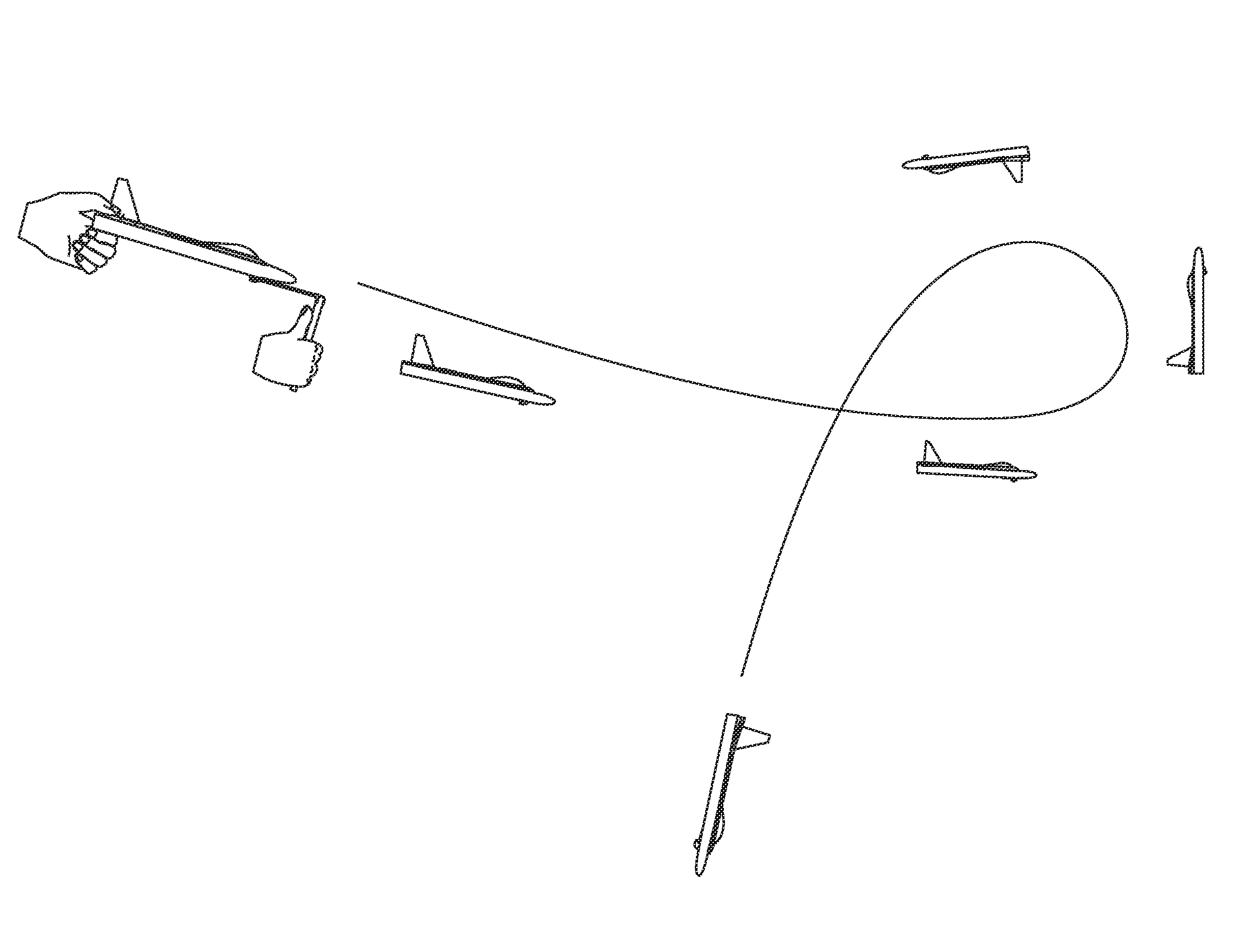
The present invention is about a toy glider fly that can reach higher altitudes and then glide down. The technical effects of this invention include easily movable horizontal tail using slow rebound foam, and stable horizontal tail movement achieved through the restoring property of slow rebound means. Additionally, the horizontal tail works stably without being affected by other factors such as spring, launching speed, air resistance, or gravity.

Problems solved by technology

There are so many devices and mechanisms successfully make toy glider fly higher as we have seen from above existing inventions, as we know heavier aircraft cannot fly higher, the maximum height that the glider can reach is depend on its total weight when under the same launch force, the existing mechanism installed for folding wings normally have relatively heavy structures for folding and opening the wings, thus the total weight increase a lot and affect flight performance inevitably.
(2) When flatten the horizontal tail in its front edge, tailgers must extend to the front from tail end, it is not comfortable for fingers to grasp, especially for children.

Method used


Image

  • Movable horizontal tail for catapult toy glider
  • Movable horizontal tail for catapult toy glider
  • Movable horizontal tail for catapult toy glider

Examples


Embodiment Construction

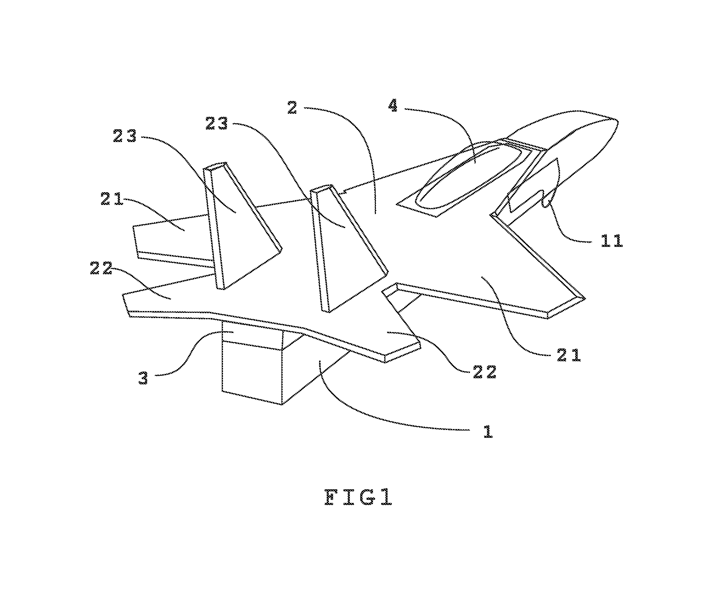
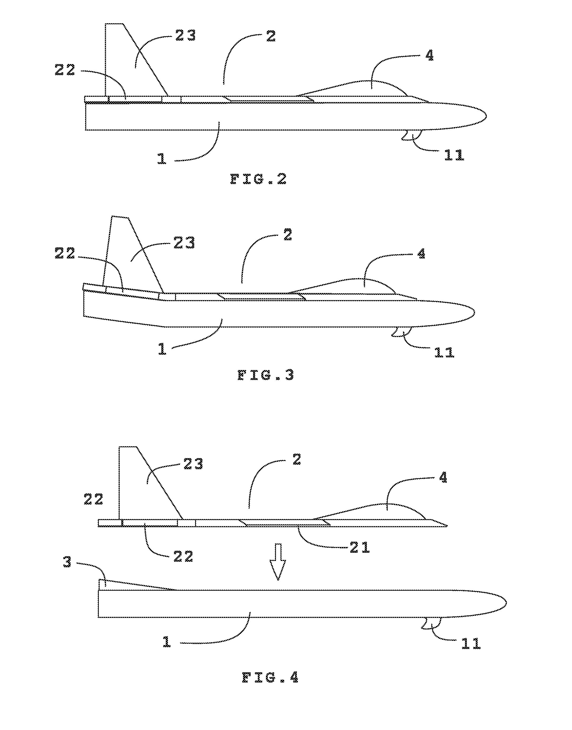
[0039]To build a movable horizontal tail glider, we starting from assembling basic aircraft components (see FIG. 1), a piece of flight control surfaces 2 which contains wings 21 and horizontal tail 22 mounted on an unbent fuselage 1 in the upper surface of the unbent fuselage 1 in rear end alignment, a set of vertical tail 23 are fixed on the rear of the flight control surfaces 2, a canopy 4 is fixed on the front end of the flight control surfaces 2 for balance, a catapult hook 11 is installed in the front bottom of the fuselage 1, The assembled glider as seen in FIG. 1 with horizontal tail 22 flat to the front wings 21 will fly a straight line when the center of gravity of the glider is balanced. When use a rear end up tilted fuselage 1 for the same assembly steps as above, as seen in FIG. 2, the horizontal tail 22 is upturned at negative angle relative to the wings 21, and the glider will travel a circular path all the time.

[0040]For a glider fly high and then circling glide down,...


PUM


Abstract

The invention relates to a horizontal tail of a catapult launched glider which can change angles during flight. An horizontal tail which can change angles means that the horizontal tail is movable, a movable horizontal tail is achieved by sandwich a slow rebound means between the horizontal tail and the fuselage, the slow rebound means could be a memory foam or a compressible plastic telescopic tube, their properties is delayed restitution when the pressure acting thereon disappears, so the horizontal tail on top of the slow rebound foam is boosted and maintained at a negative angle with the longitudinal axis of the fuselage when there is no pressure acting on it, the compressible slow rebound means allows the horizontal tail be pressed downward from negative angle to zero angle or even to positive angle when squeeze the tail portion of the glider by fingers before launch, the horizontal tail is maintained at zero angle or positive angle at that time, after launch, the horizontal tail moves towards negative angle with a slow speed which is controlled by the expansion rate of the slow rebound means, the glider travels in the sky with a nearly straight upward climb first, then go down with a smooth gliding and landing as the horizontal tail has been propped up by the slow rebound means. Another play mode is by griping the sides of the fuselage without touching the horizontal tail, the glider will fly in circles.

Description

BACKGROUND OF THE INVENTION[0001]1. Field of the Invention[0002]The invention generally relates to a horizontal flight control device of a catapult toy glider, more particularly, the invention relates to a lightweight design be installed on existing toy glider to make horizontal tail can move further to allow the toy glider to climb as high as possible and then glide down gently.[0003]2. Description of the Related Art[0004]Fly to high altitude and glide down slowly is people's desire about a glider. Because catapult launch with very fast initial speed, launch toward the sky are the benefits attached to the catapult launch for onlookers and bystanders. In order to make the glider fly high, some use folding wings to reduce launch resistance, some use movable horizontal tail to control the flight locus, both approaches obtained the goal of vertical rise fly.[0005]The existing inventions use folding wings mechanism such as disclosed in the following patents: U.S. Pat. No. 2,078,374A (Jo...

Claims


Application Information

Patent Timeline
IPC IPC(8): A63H27/14
CPCA63H27/14
Inventor TSAI, TZU-JAN
Owner TSAI TZU JAN
Learn More