
System and apparatus for supportive scaffolding

Inactive Publication Date: 2010-04-15
GENERAL STEEL PRODS
View PDF46 Cites 1 Cited by
  • Summary
  • Abstract
  • Description
  • Claims
  • Application Information

AI Technical Summary

Benefits of technology

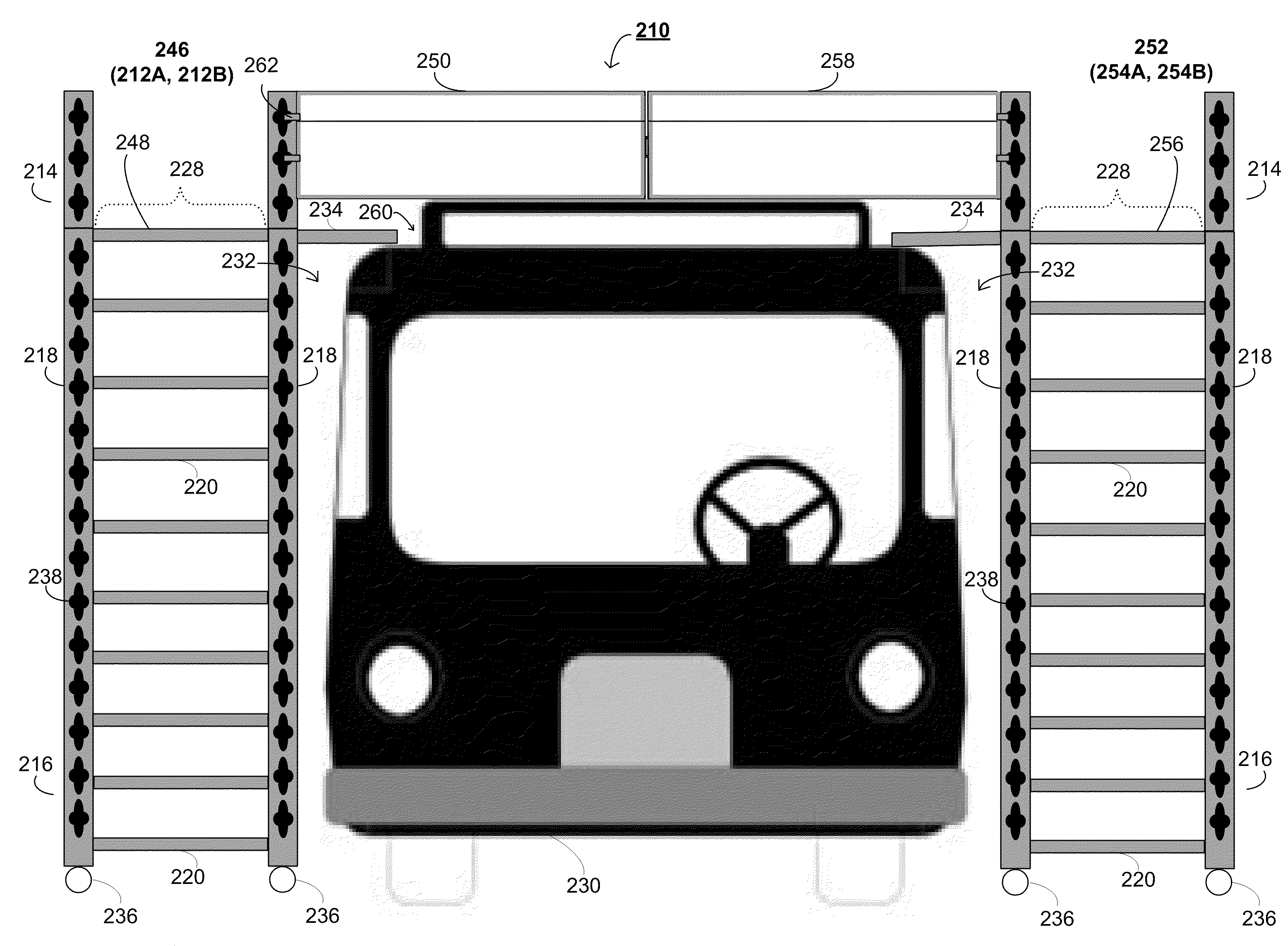
[0014]The invention may be implemented to realize one or more of the following advantages. The scaffold system may be easily movable and positioned around any number of structures. Also, it may include gap fillers to provide users with safe passage between the scaffold system and a structure by diminishing the chance that a user could fall between the scaffold and the structure. Further, the scaffold system may include gates that, when interfaced with each other and a railing along the scaffolding, may provide a 360-degree zone of safety (e.g., boundary) within which users may safely access the top of a structure.

Problems solved by technology

However, scaffold systems in the art share similar deficiencies with regard to providing users with safe access to the structures.
For example, due to the shape of many structures, the scaffold system may not be able to be positioned close to the structure where access may be needed.
This may create a gap between the scaffold and the structure through which a user could fall.
Further, while scaffold may be positioned on opposite sides of a structure, they may not provide a 360-degree zone of safety for users on top of the structure.
Moreover, these scaffold systems lack the ability to integrate with each other to create boundaries for the users.

Method used


Image

  • System and apparatus for supportive scaffolding
  • System and apparatus for supportive scaffolding
  • System and apparatus for supportive scaffolding

Examples


Embodiment Construction

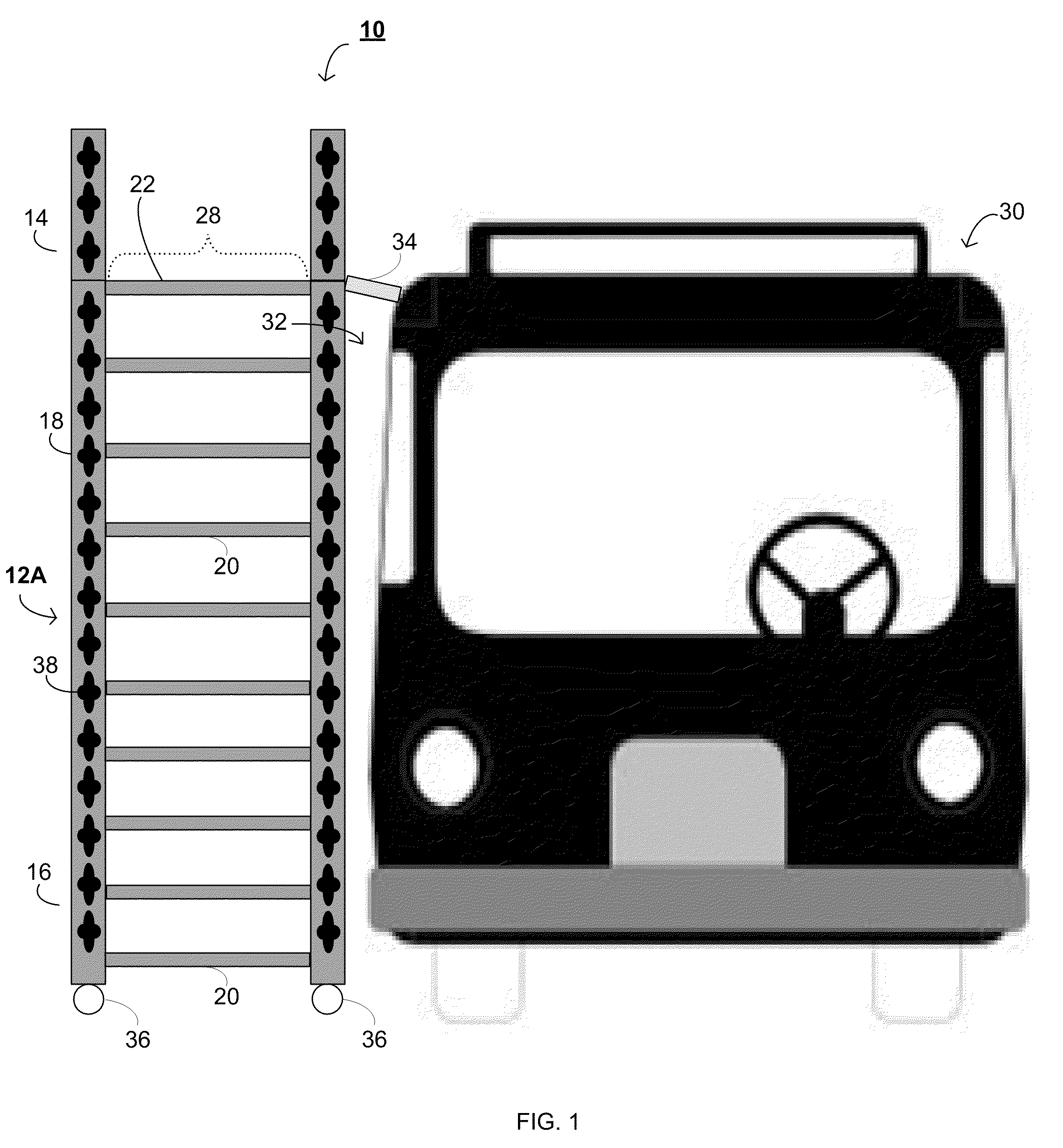
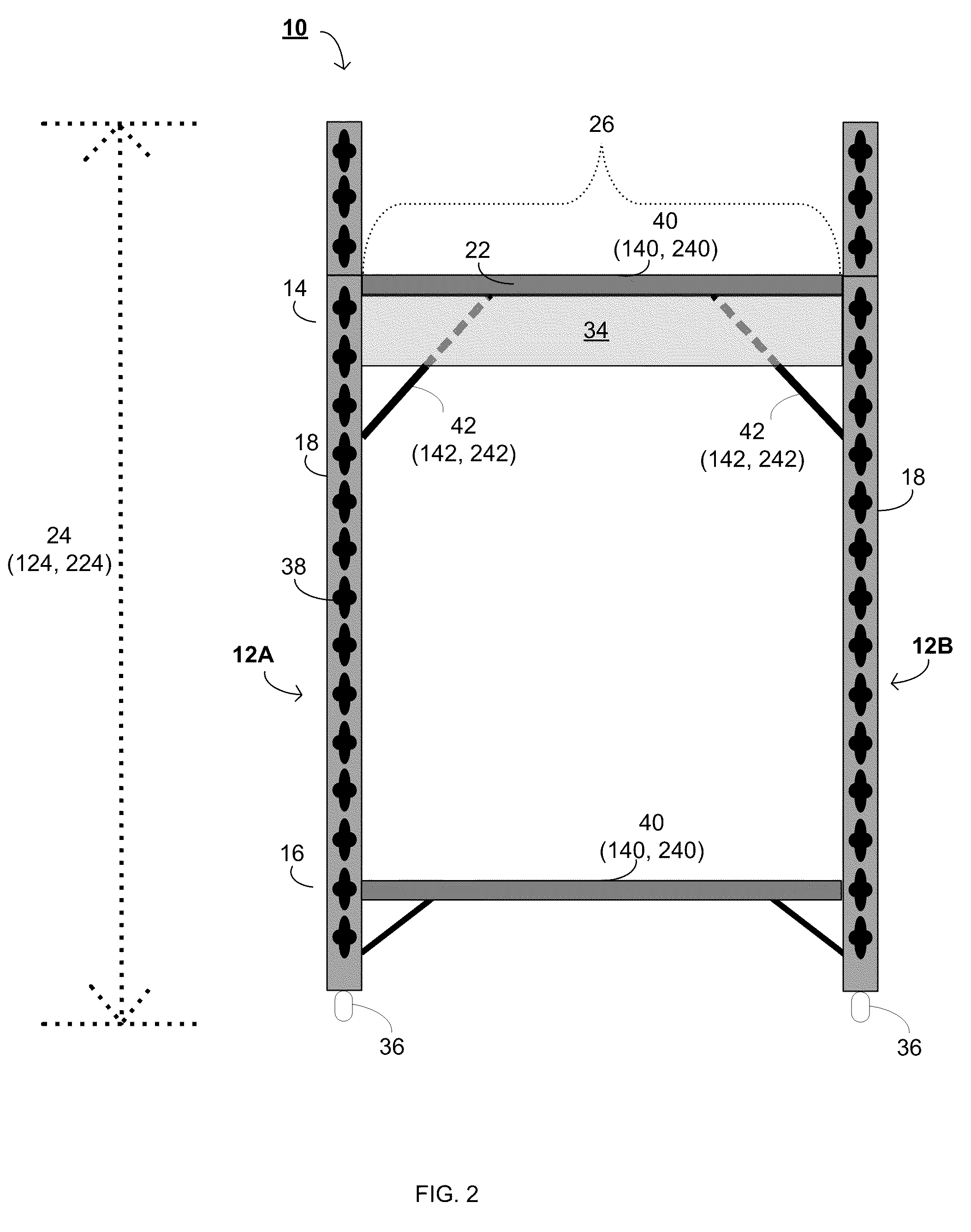
[0022]Referring to FIGS. 1 & 2, there is shown an embodiment of a scaffold system 10. The scaffold system 10 may include at least two essentially vertical support assemblies 12A and 12B having an upper end 14 and a lower end 16. Each of the essentially vertical support assemblies 12A and 12B may include at least two vertical support members 18 connected by at least one horizontal member 20. The vertical support members 18 may be composed of steel angles, and may be metal inert gas (MIG) welded together with the horizontal member 20. The horizontal member 20 may be composed of one (1) inch steel pipe.

[0023]The essentially vertical support assemblies 12A and 12B may also include a plurality of horizontal members 20. The horizontal members 20 may be configured to be attached to the vertical support members 18 to enable a user to access a platform 22. The horizontal members 20, when positioned along a height 24 of the vertical support members 18, may be configured to form a ladder. The ...


PUM


Abstract

A scaffold system includes at least two essentially vertical support assemblies having an upper end and a lower end, wherein each essentially vertical support assembly includes at least two vertical support members connected by at least one horizontal member. A platform is attached proximate to the upper ends of the at least two essentially vertical support assemblies, wherein the vertical support assemblies are positioned to be proximate to a structure. One or more gap fillers are movably attached adjacent to the platform along at least a portion of the platform length and are configured to extend at least a portion of the platform towards the structure. One or more movable gates are attached to the essentially vertical support assemblies of one or more movable scaffolds, wherein the movable scaffolds are configured to be positioned on opposite sides of the structure to enable access to a top of the structure, and the movable gates may be connected to each other over the top of the structure.

Description

TECHNICAL FIELD[0001]This disclosure relates to scaffold systems, and more particularly, to scaffold systems incorporating gap fillers and / or gates.BACKGROUND[0002]Scaffold systems are generally well-known in the art for providing users with access to structures that would not be achievable from ground-level. The composition of scaffold systems may vary greatly, as any materials that may support a user above ground-level may constitute such a system. However, scaffold systems in the art share similar deficiencies with regard to providing users with safe access to the structures. For example, due to the shape of many structures, the scaffold system may not be able to be positioned close to the structure where access may be needed. This may create a gap between the scaffold and the structure through which a user could fall. Further, while scaffold may be positioned on opposite sides of a structure, they may not provide a 360-degree zone of safety for users on top of the structure. Mor...

Claims


Application Information

Patent Timeline
IPC IPC(8): E04G1/04
CPCE04G1/24E04G1/14E04G2001/242
Inventor MELTZ, GEORGE R.MELTZ, STEVEN Y.LOPEZ, DAVID E.
Owner GENERAL STEEL PRODS
Learn More