Hinge device for doors, shutters and the like

a technology for shutters and doors, applied in door/window fittings, wing openers, constructions, etc., can solve the problems of not allowing the adjustment of the closing speed, unsatisfactory aesthetic appeal, and not allowing simple and quick adjustment, so as to achieve simple construction, high functionality, and low cost

Active Publication Date: 2015-08-20
IN & TEC
View PDF28 Cites 18 Cited by
  • Summary
  • Abstract
  • Description
  • Claims
  • Application Information

AI Technical Summary

Benefits of technology

[0008]An object of the present invention is to overcome at least partly the above mentioned ...

Problems solved by technology

All these known devices are more or less bulky, and consequently they have an unpleasant aesthetic appeal.
Moreover, they do not allow for adjustment of the closing speed and/or of the latch action of the door, or in an...

Method used


Image

  • Hinge device for doors, shutters and the like
  • Hinge device for doors, shutters and the like
  • Hinge device for doors, shutters and the like

Examples


Embodiment Construction

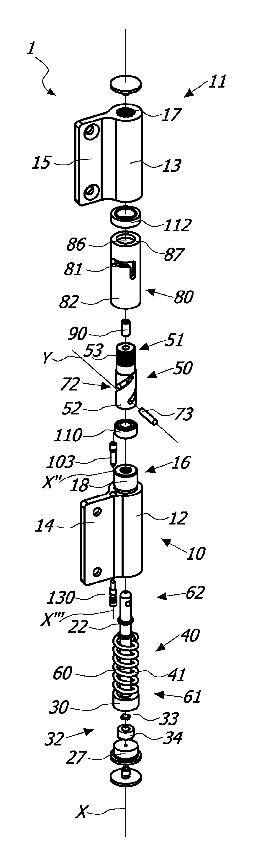
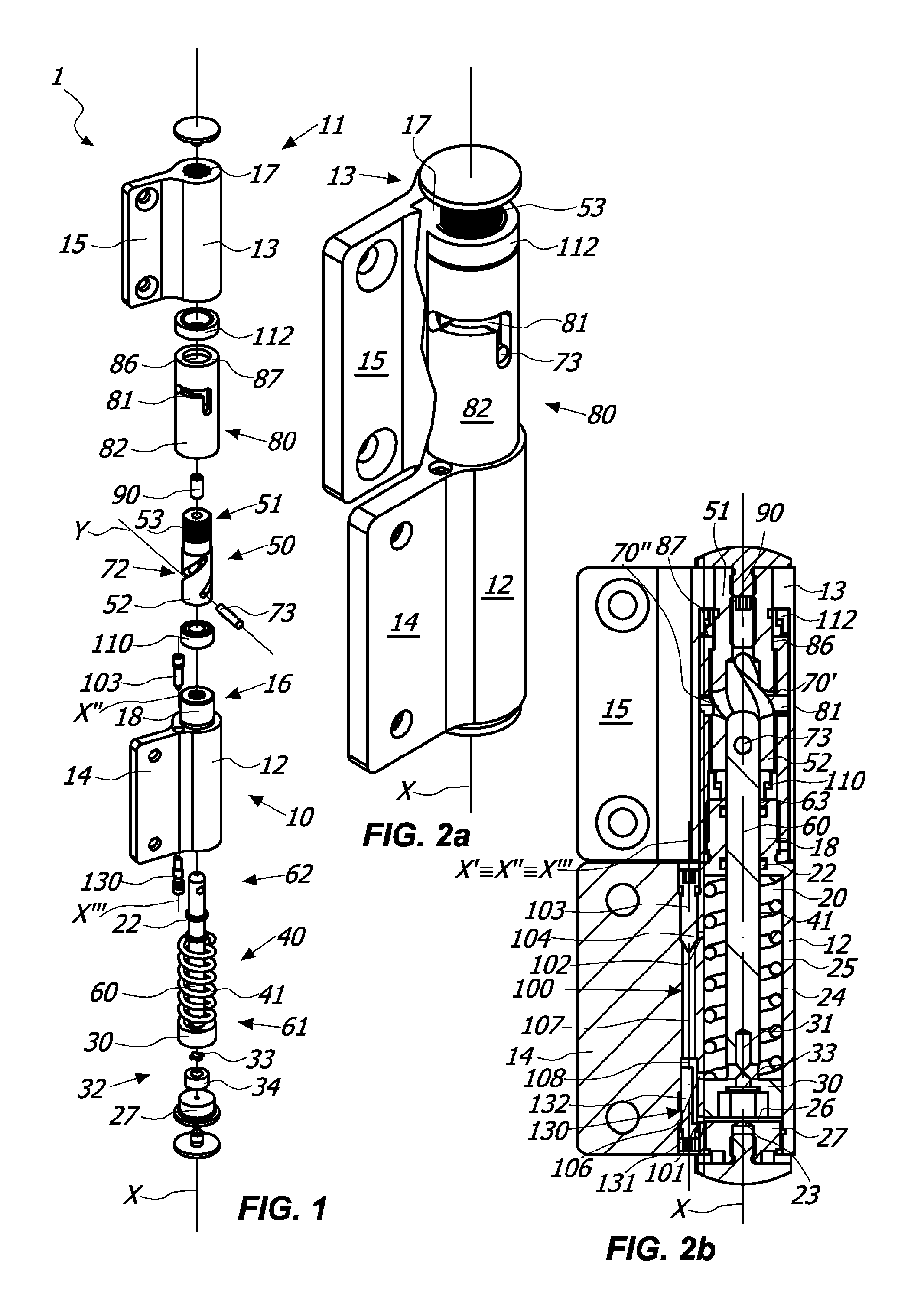
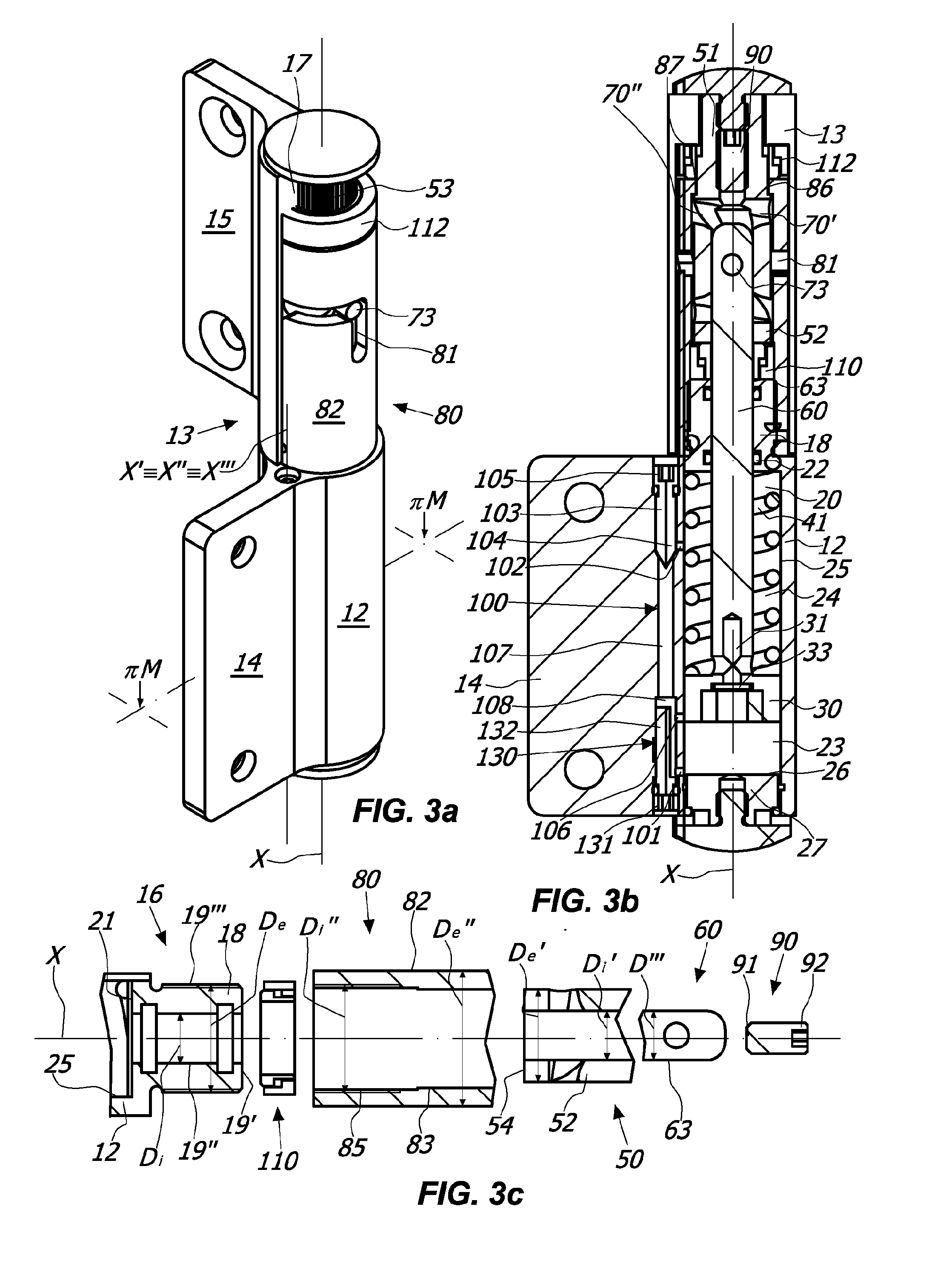
[0066]With reference to the above figures, the hinge device according to the invention, generally indicated with 1, is particularly useful for rotatably moving and / or controlling a closing element D, such as a door, a shutter, a gate or the like, which can be anchored to a stationary support structure S, such as a wall and / or a door or window frame and / or a support pillar and / or the floor.

[0067]Depending on the configuration, the hinge device 1 according to the invention allows only the automatic closing of the closing element D to which it is coupled, as shown in FIGS. 30 to 34c, or only the control during opening and / or closing thereof, as shown for example in FIGS. 22 to 25b, or both actions, as shown in FIGS. 1 to 5c.

[0068]In general, the hinge device 1 may include a fixed element 10 anchored to the stationary support structure S and a movable element 11 which may be anchored to the closing element D.

[0069]In a preferred, not exclusive embodiment, the fixed element 10 may be po...


PUM


Abstract

A hinge device includes a first fixed tubular half-shell having a working chamber defining a longitudinal axis, a second tubular half-shell rotatable about the longitudinal axis, a pivot rotating unitarily with the latter which includes a single pass-through actuating member having a helical shape, a plunger member slidable along the longitudinal axis, and a tubular bushing having a pair of guide cam slots. A pin inserted within the pass-through actuating member is provided to allow the mutual engagement of the pivot and the bushing. The first tubular half-shell includes an end portion susceptible to rotatably support the pivot, the second tubular half-shell and the bushing are coaxially coupled to each other, and the bushing and the first tubular half-shell are mutually unitarily coupled.

Description

FIELD OF INVENTION[0001]The present invention is generally applicable to the technical field of the closing and / or control hinges for doors, shutters or like closing elements, and particularly relates to a hinge device for rotatably moving and / or controlling during closing and / or opening a closing element, such as a door, a shutter or the like, anchored to a stationary support structure, such as a wall or a frame.BACKGROUND OF THE INVENTION[0002]As known, hinges generally include a movable member, usually fixed to a door, a shutter or the like, pivoted onto a fixed member, usually fixed to the support frame thereof, or to a wall and / or to the floor.[0003]From documents U.S. Pat. No. 7,305,797, EP1997994 and US2004 / 206007 hinges are known wherein the action of the closing means that ensure the return of the door in the closed position is not damped. From document EP0407150 is known a door closer which includes hydraulic damping means for damping the action of the closing means.[0004]...

Claims


Application Information

Patent Timeline
IPC IPC(8): E05F3/20
CPCE05F1/1223E05F3/12E05Y2201/412E05Y2201/638E05Y2800/296E05F3/20
Inventor BACCHETTI, LUCIANO
Owner IN & TEC
Why Eureka
Try Eureka