Accumulator

a technology of accumulator and air chamber, which is applied in the field of accumulator, can solve the problems of reducing production efficiency and excessive pressure of the air chamber of the accumulator, and achieve the effects of improving sealing performance, reducing machining man-hours, and cross-sectional area

Active Publication Date: 2015-08-27
NHK SPRING CO LTD
View PDF9 Cites 7 Cited by
  • Summary
  • Abstract
  • Description
  • Claims
  • Application Information

AI Technical Summary

Benefits of technology

[0031]Since the accumulator according to the present invention is adapted to arrange the port part on one end face portion of the shell and to support the base end portion of the bellows on another end face portion of the shell to thereby enable a cross-sectional area on the fluid chamber side to be enlarged because the bellows is arranged on the air chamber side, an area of an end face of the flange portion can be enlarged to improve the sealing performance on the seal face.
[0032]The accumulator according to the present invention makes it possible to reduce a machining man-hour with a simple configuration; to prevent damage of the self-sealing member and improve durability thereof to realize a stable and reliable operation of the accumulator in the normal operation; and to release an internal pressure of the air chamber quickly and reliably in the non-normal operation in which the temperature rises more excessively than in the normal operation.

Problems solved by technology

Such an accumulator has heretofore had a possibility that an internal pressure of the air chamber of the accumulator excessively increases, for example, when the automobile encounters a fire or the like to be placed in a high-temperature environment for a long time.
However, the accumulator described in Patent Document 1 has posed problems in that machining of the fragile portion 11 is complicated and thus accuracy control for the machining is required to increase a machining man-hour and to decrease production efficiency.

Method used


Image

  • Accumulator
  • Accumulator
  • Accumulator

Examples


Embodiment Construction

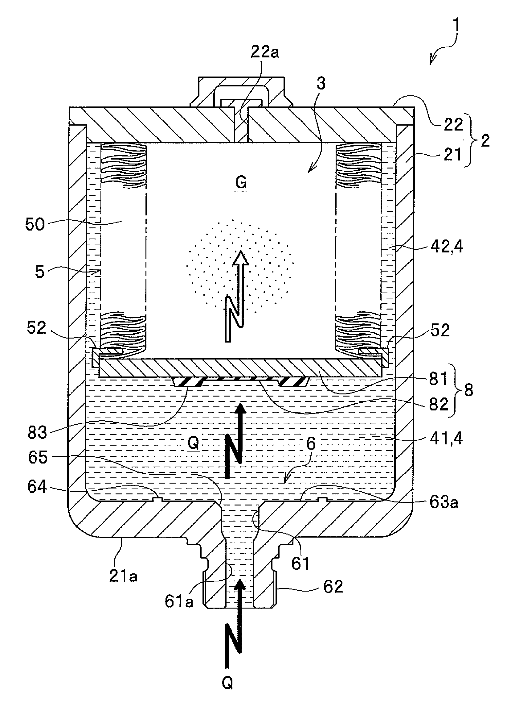
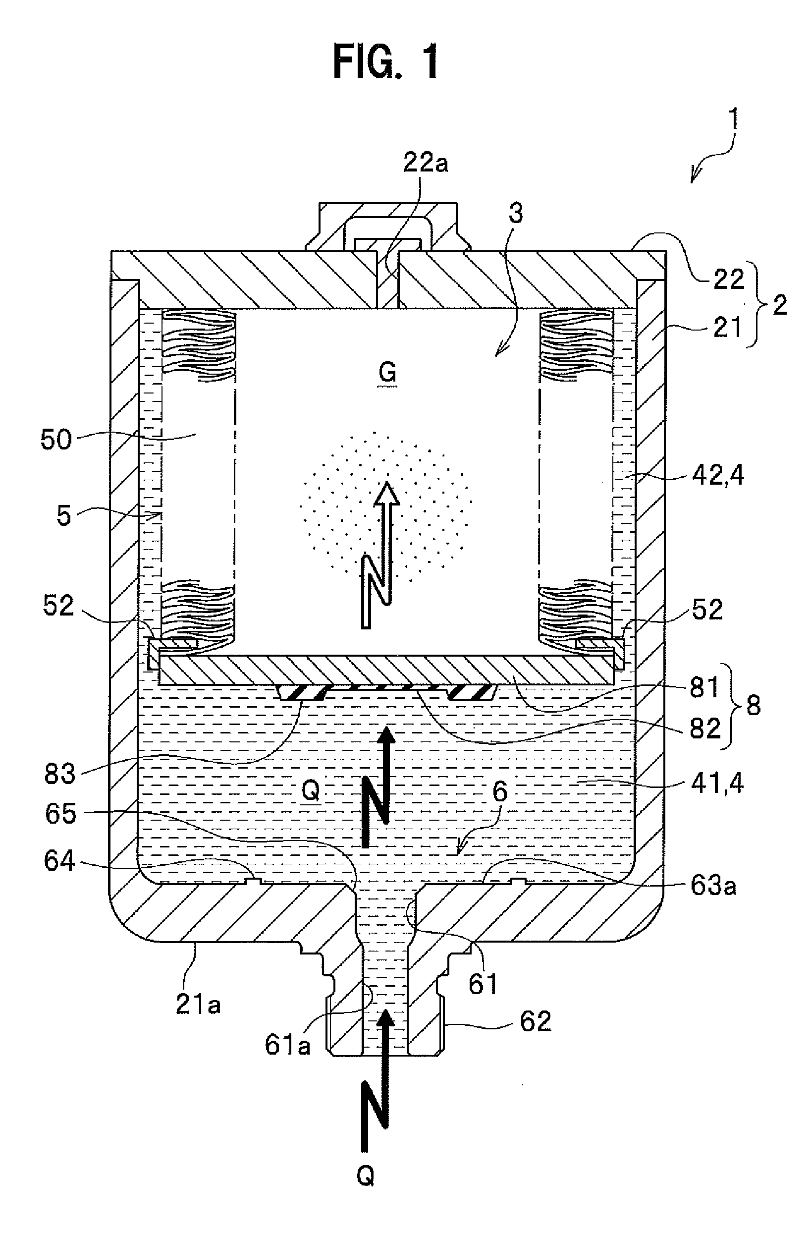
[0043]A configuration of an accumulator 1 according to an embodiment of the present invention will be described in detail with reference to FIGS. 1 to 3 as appropriate.

[0044]As shown in FIG. 1, the accumulator 1 is provided with a shell 2 comprised of a pressure vessel, an air chamber 3 which is formed inside the shell 2 and in which high-pressure gas G is filled, a fluid chamber 4 into which pressure fluid Q is introduced from a fluid-pressure circuit (not shown) such as a braking circuit, a bellows 5 which is housed to freely expand and contract in the shell 2, a bellows guide 52 which slidably supports the bellows 5, a port part 6 of the shell 2 in which a pressure fluid inflow port 61 that is open to the fluid chamber 4 is formed, and a self-sealing member 8 which is arranged on a tip portion of the bellows 5.

[0045]The self-sealing member 8 is arranged on the tip portion of an elastic part 50 of the bellows 5 to face the port part 6 and has a function of sealing the tip portion ...


PUM


Abstract

An accumulator includes a bellows housed to freely expand and contract in a shell, a port part having a pressure fluid inflow port formed therein, and a self-sealing member arranged on a tip portion of the bellows to face the port part, in which when a pressure in the fluid chamber is lower than a predetermined pressure relative to an air chamber, the self-sealing member is allowed to abut onto a seal area of the port part to block the pressure fluid inflow port. The self-sealing member includes a resilient member arranged on a surface of a base material part, and an overhanging portion formed on the resilient member and allowed to abut onto the seal area for sealing. The port part includes a seal face having the seal area formed thereon, and a projecting portion arranged on a region other than the seal area on the seal face.

Description

CROSS-REFERENCE TO RELATED APPLICATION[0001]This application is based upon and claims the benefit of priority to the Japanese Patent Application No. 2014-032916, filed on Feb. 24, 2014, the entire contents of which are incorporated herein by reference.BACKGROUND OF THE INVENTION[0002]1. Field of the Invention[0003]The present invention relates to an accumulator, more particularly, to an accumulator that is adapted, in a non-normal operation in which a pressure and a temperature in an air chamber increase more excessively than in a normal operation, to release the pressure in the air chamber through a gap portion formed between a self-sealing member and a seal face facing the self-sealing member.[0004]2. Description of the Related Art[0005]A fluid-pressure circuit such as a braking circuit used in an automobile employs an accumulator that temporarily accumulates pressurized fluid. Formed in the accumulator are an air chamber adapted to allow high-pressure gas to be filled therein, an...

Claims


Application Information

Patent Timeline
Patent Type & Authority Applications(United States)
IPC IPC(8): F15B1/10B60T17/06F16L55/053
CPCF15B1/103B60T17/06F16L55/053F15B1/083
Inventor MIZUKAMI, HIROSHI
Owner NHK SPRING CO LTD
Why Eureka
Try Eureka