System for radiographic inspection of welds

Active Publication Date: 2015-08-27
ROENTGEN TECHNISCHE DIENST BV
View PDF4 Cites 6 Cited by
  • Summary
  • Abstract
  • Description
  • Claims
  • Application Information

AI Technical Summary

Benefits of technology

The invention provides a stable frame for a radiation system that can be used for dynamic scanning with a lower risk of vibration. The frame is rigidly connected between two subframes and has optional limited movement perpendicular to the plates. The system can switch between horizontal and vertical welds and maintain stable alignments between the detector and the source to avoid influencing image quality. Additionally, the support wheels can be optimized for stability during scanning.

Problems solved by technology

No dynamic / scanning systems are available yet.

Method used


Image

  • System for radiographic inspection of welds
  • System for radiographic inspection of welds
  • System for radiographic inspection of welds

Examples


Embodiment Construction

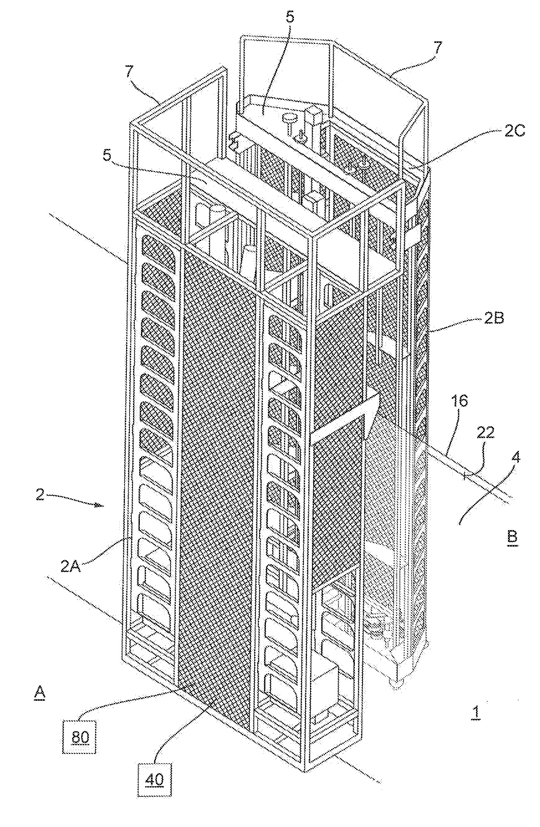
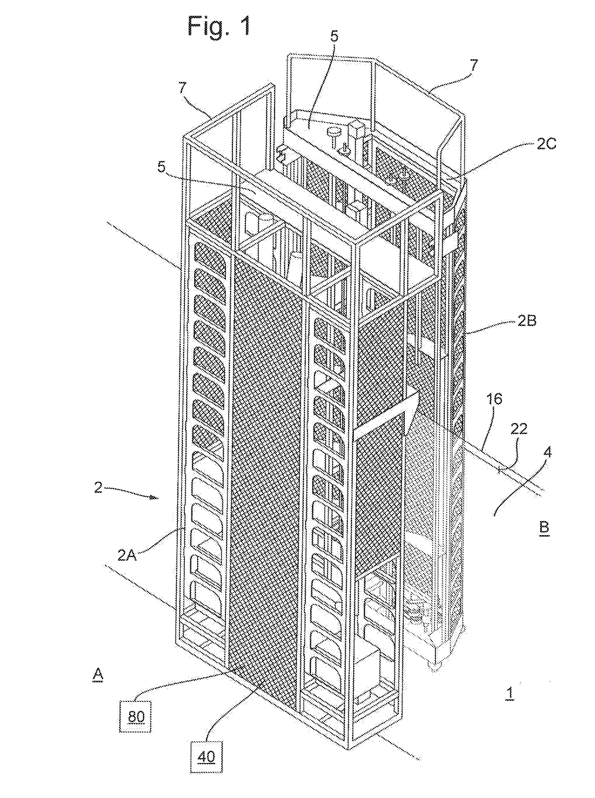
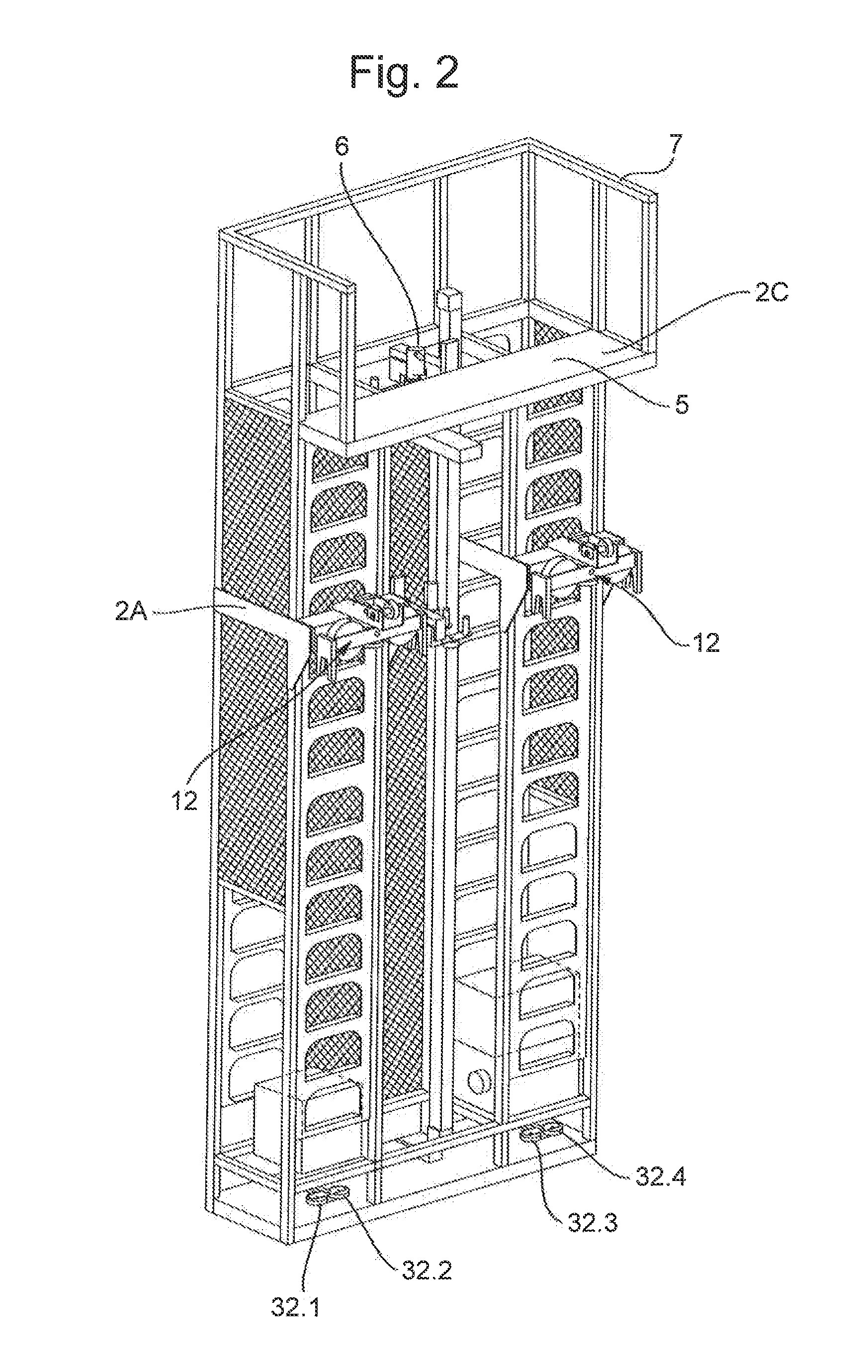
[0093]In FIG. 1 reference number. 1 indicates a system for radiographic inspection of at least a portion of a vertical wall such as the wall of a storage tank for gas or oil. The system 1 comprises a frame 2 which comprises a first sub frame 2A arranged to be positioned in use, on a first side A of a portion of the wall 4. The frame 2 further comprises a second sub frame 2B arranged to be, in use, on a second side B of the portion of the wall 4, which lays opposite to the first side A of the portion of the wall 4. Each of the sub frames 2A, 2B extends downwardly from a top portion 2C of the frame 2. In this example the top portion 2C is formed by the floors 5 on top of the first sub frame and the second sub frame respectively and which are each at least partially surrounded by a fence 7. The system further comprises a radiation source 6 which is attached to the first sub frame 2A for transmitting electromagnetic radiation towards a weld of the wall 4. Furthermore the system comprise...


PUM

PropertyMeasurementUnit
Timeaaaaaaaaaa
Timeaaaaaaaaaa
Angleaaaaaaaaaa

Abstract

A system for radiographic inspection of welds from at least a portion of a vertical wall such as the wall of a storage tank for gas or oil wherein the wall comprising a plurality of metal plates connected by means of the welds, the system comprising a frame comprising a first sub frame arranged to be positioned, in use, on a first side of the portion of the wall and a second sub frame arranged to be positioned, in use, on a second side of the portion of the wall which lays opposite to the first side of the portion of the wall. The system comprises a radiation source which is attached to the first sub frame for transmitting electromagnetic radiation towards the weld and a radiation detector which is attached to the second sub frame for detecting radiation which has travelled through the weld for carrying out the inspection.

Description

[0001]The present invention relates to a system for radiographic inspection of welds from at least a portion of a vertical wall such as the wall of a storage tank for (liquefied) gas or oil wherein the wall comprising a plurality of metal plates connected by means of the welds, the system comprising a frame comprising a first sub frame arranged to be positioned, in use, on a first side of the portion of the wall and a second sub frame arranged to be positioned, in use, on a second side of the portion of the wall which lays opposite to the first side of the portion of the wall wherein the system comprises a radiation source which is attached to the first sub frame for transmitting electromagnetic radiation towards the weld and a radiation detector which is attached to the second sub frame for detecting radiation which has travelled through the weld for carrying out the inspection.BACKGROUND OF THE INVENTION[0002]Such a system is known from U.S. Pat. No. 4,490,833. The system is used ...

Claims


Application Information

Patent Timeline
IPC IPC(8): G01N23/18B23K31/12
CPCB23K31/125G01N23/18G01N2223/629G01N2223/631G01N23/083
Inventor MOLENAAR, MARCEL MEIJLOMHARTWIGSEN, MARTIN ANDERMULDER, BERNARDUS NORBERTUS
Owner ROENTGEN TECHNISCHE DIENST BV
Why Eureka
Try Eureka