Multiple position earphone cable exit

Inactive Publication Date: 2016-06-16
DEKALB FREDERICK
View PDF1 Cites 6 Cited by
  • Summary
  • Abstract
  • Description
  • Claims
  • Application Information

AI Technical Summary

Benefits of technology

[0003]This invention provides a simple but very effective solution to this problem. The earphone cable can easily be moved from a lower position to an upper position of an earpiece (or visa versa) and retained there. The cable also exits close (about parallel) to the side of the face, for optimum stability. Thus, the invention provides a movable earphone or headphone cable between a plurality of positions that is retained in that position. Some o

Problems solved by technology

There are a small number of earphones/headphones that can be switched from the upper orientation to the lower

Method used


Image

  • Multiple position earphone cable exit
  • Multiple position earphone cable exit
  • Multiple position earphone cable exit

Examples


Example

EXAMPLE

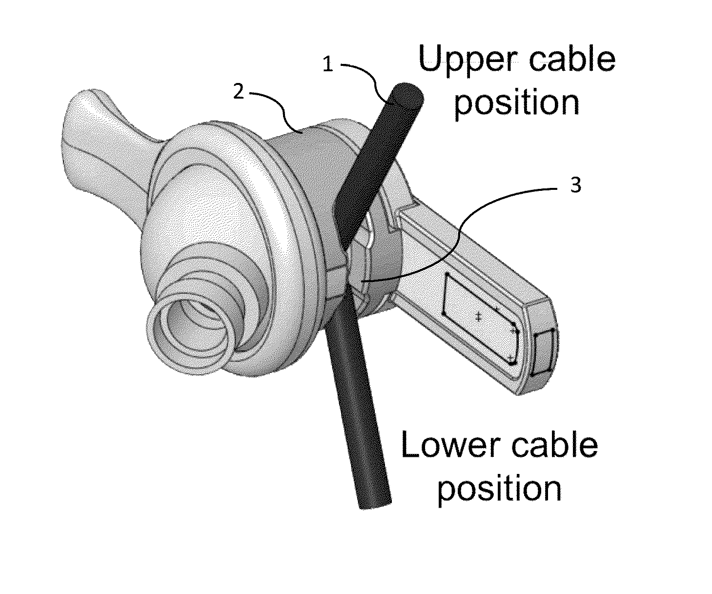
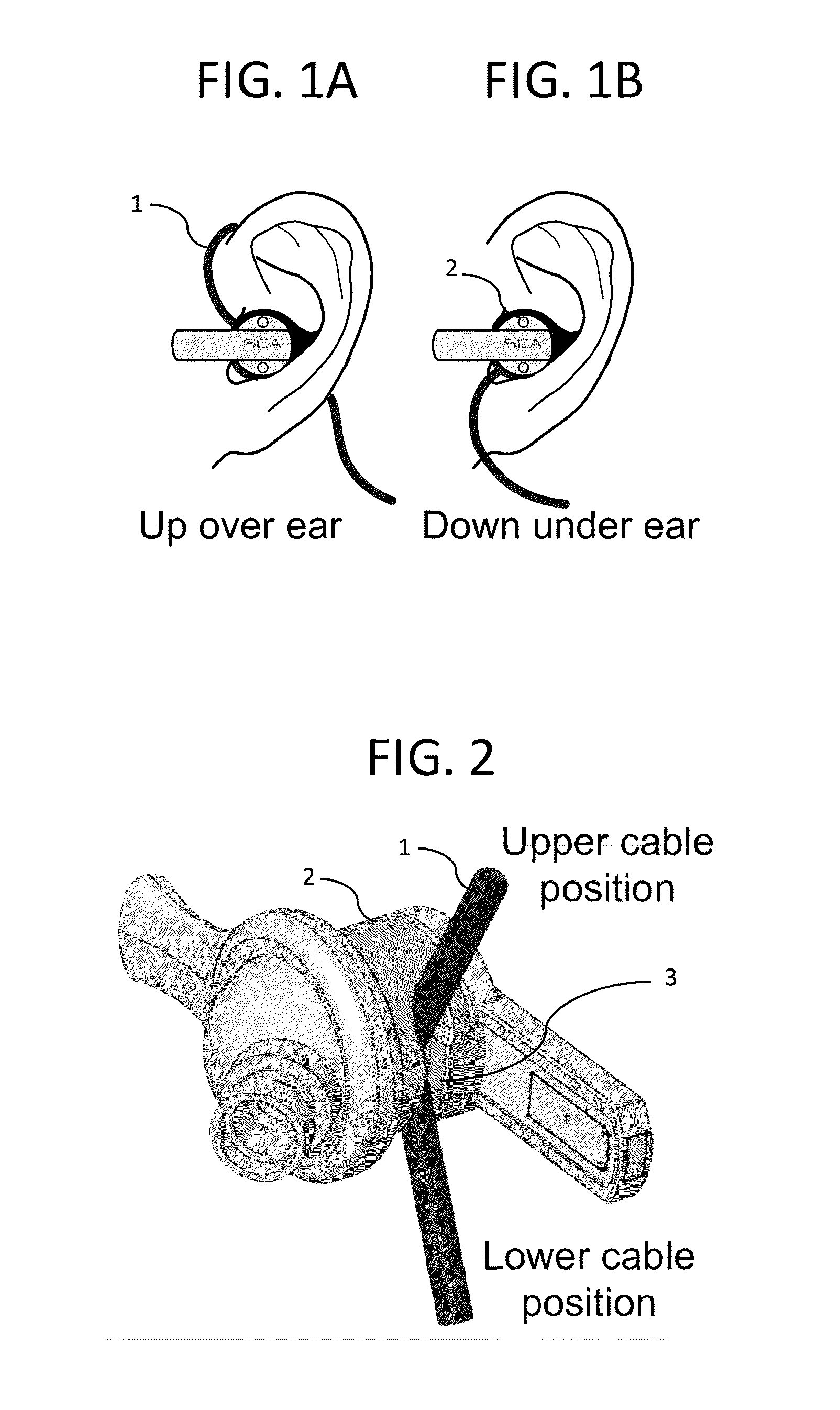
[0032]An exemplary earpiece of the invention was made as follows and illustrated in

[0033]FIGS. 1-3. In FIG. 1, an earpiece sits in the ear with the wire 1 extending from the body 2 in an up detent position or a down detent position. FIG. 2 shows the same earpiece outside of an ear with the wire 1 extending from the body 2 in an up or down detent position. A slot 3 allows movement of the wire 1 to the detent positions. The wire 1 is retained in the positions by the narrowing of the slot between the positions. This results in resistance to wire movement but not prevention of said movement.

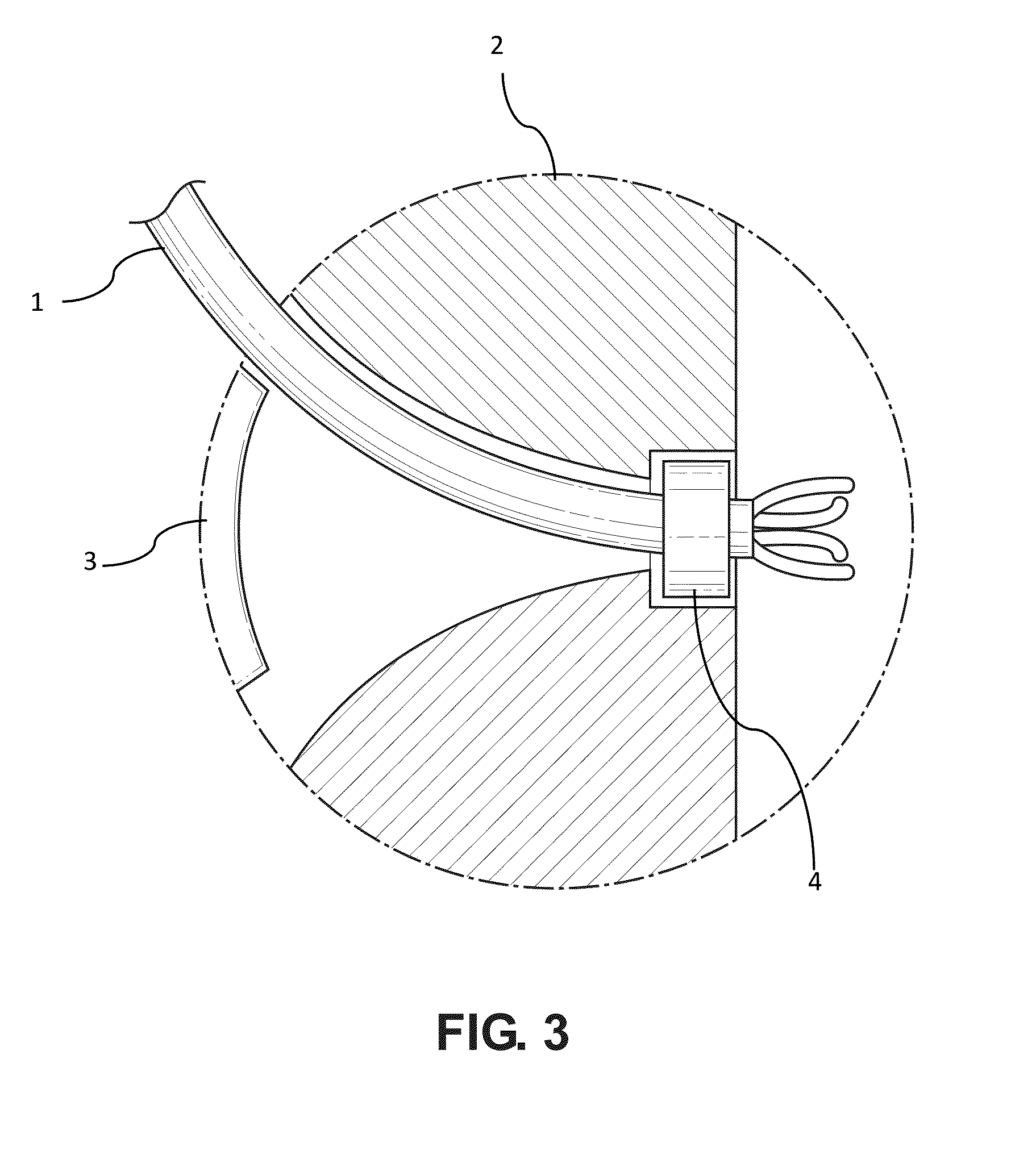
[0034]FIG. 3 shows a cross section of the body 2 and the positioning of the wire 1 and slot 3. A retainer such as a crimp 4 keeps the wire in the body 2 and prevents disconnection from a circuit that includes a speaker and optionally other electronic audio components inside the earpiece. Other embodiments of the retainer 4 may include a movable housing that rotates with the wire but retains th...


PUM


Abstract

The invention provides earphones that provide a user with a choice of selectable, stable positions from which a wire exits the earphone. When the wire exits in an “up” position, it favors winding over the ear to a source or transmitter of electrical sound information. When the wire exits in a “down” position, it does not favor winding over the ear. The wire exits the earphone about parallel to the side of the user's face so that it does not protrude in an unsightly or unstable manner.

Description

FIELD OF THE INVENTION[0001]The invention relates to earphones that provide a user with a choice of selectable, stable positions from which a wire exits the earphone.BACKGROUND OF THE INVENTION[0002]Earpieces used for earphones (also called in-ear headphones or in-ear monitors) have a cable that can exit downwards below the ear or upwards, over and behind the ear. The cable is usually fixed in one of these orientations and cannot be switched between them. There are a small number of earphones / headphones that can be switched from the upper orientation to the lower orientation but they do so with swivels on the outside of the earpiece resulting in a bulky, unstable earphone.SUMMARY OF THE INVENTION[0003]This invention provides a simple but very effective solution to this problem. The earphone cable can easily be moved from a lower position to an upper position of an earpiece (or visa versa) and retained there. The cable also exits close (about parallel) to the side of the face, for op...

Claims


Application Information

Patent Timeline
IPC IPC(8): H04R1/10
CPCH04R1/1033H04R1/1016H04R2460/01H04R2460/15H04R1/1083G10K2210/1081G10K2210/3222G10K11/17881G10K11/17857G10K11/17885G10K11/17821G10K11/17873G10K11/17861
Inventor DEKALB, FREDERICK
Owner DEKALB FREDERICK
Why Eureka
Try Eureka