Opto-electric phase-locked loop for recovering the clock signal in a digital optical transmission system

Inactive Publication Date: 2007-07-19
FRAUNHOFER GESELLSCHAFT ZUR FOERDERUNG DER ANGEWANDTEN FORSCHUNG EV
View PDF13 Cites 23 Cited by
  • Summary
  • Abstract
  • Description
  • Claims
  • Application Information

AI Technical Summary

Benefits of technology

[0008] Based upon the closest prior art, the object of the present invention is to be seen in further to develop a phase-locked loop of the kind referred to supra so that precise recovery of the clock signal from high-rate clocked data signals with as low a time jitter of the phase position as possible can be achieved and an optimum latching stability of the phase-locked loop i

Problems solved by technology

Instead of a genuine mathematical differentiation it is, however, only possible to perform a discrete differentiation (without normalizing).
In view of the fact that narrower switching windows are required, it is more difficult to extract the clock signal from such signal rates with the known phase-locked loops.
Usually, these switching windows result in lower switching contrast and, therefore, to worse signal-to-noise-ratio.
As a result of the absence of normalization (division by Δt) the derived differential control signal is relatively weak, howeve

Method used


Image

  • Opto-electric phase-locked loop for recovering the clock signal in a digital optical transmission system
  • Opto-electric phase-locked loop for recovering the clock signal in a digital optical transmission system
  • Opto-electric phase-locked loop for recovering the clock signal in a digital optical transmission system

Examples


Example

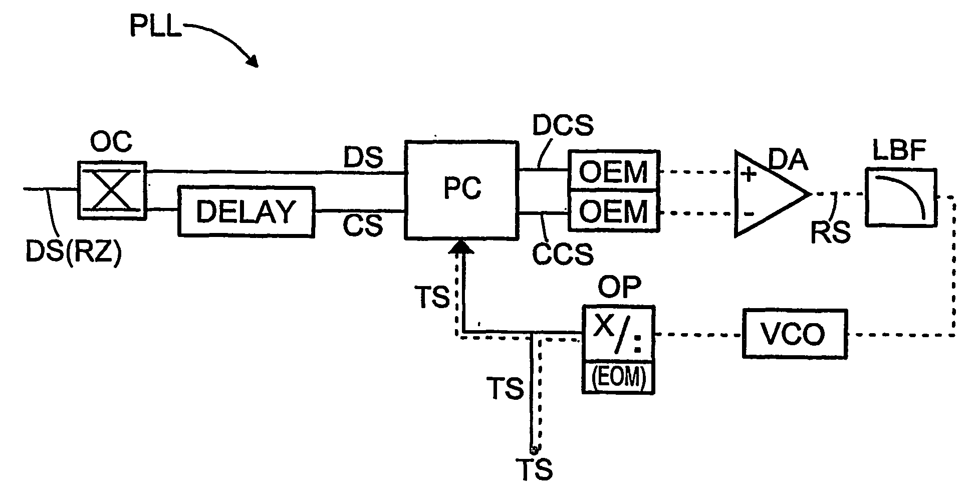
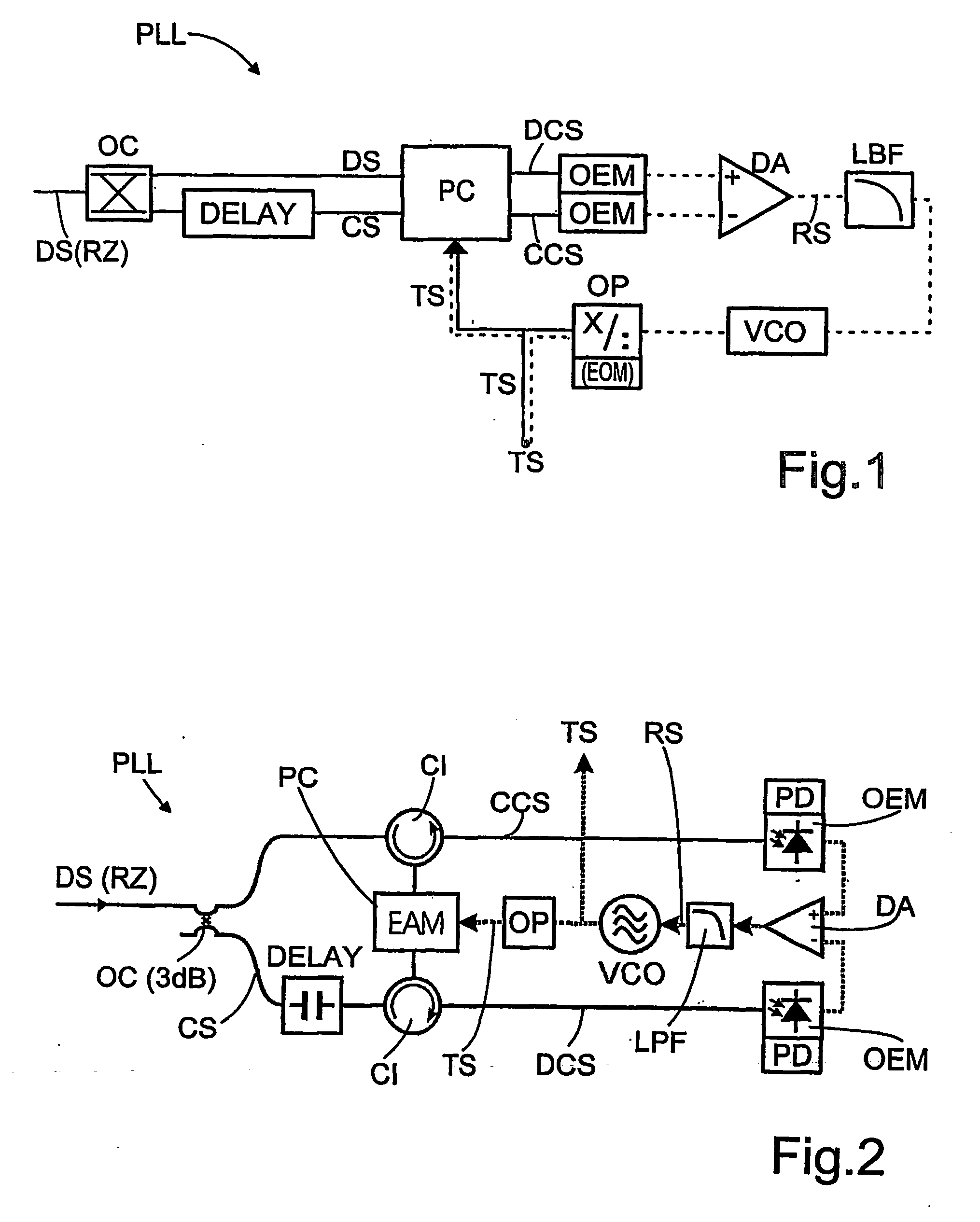
[0027]FIG. 1 schematically depicts an opto-electric phase-locked loop PLL by means of which the clock signal TS of an optical time division multiplexed (OTDM) data signal DS transmitted at a high frequency with return-to-zero RZ data pulses can be safely recovered. The optical paths are shown in solid lines, the electrical paths are shown in dashed lines. For the clock recovery, an output signal CS is initially generated by way of an optical extractor OC. This is fed through a phase delay element DELAY and is thus shifted in its phase relative to the data signal DS. Alternatively, the data signal DS may be fed through the phase delay element DELAY since it is only the relative phase shift between the two signals DS, CS which matters. The height and-shape of the switching window may be affected by the size set for the phase shift, preferably between ⅙ and ½ of the data signal period. The data signal DS as well as the output signal CS are fed unidirectionally or counterdirectionally t...


PUM


Abstract

A phase-locked loop for a differential recovery of the clock signal wherein an extracted data signal (DS) is conveyed via a phase delay element and thence to a phase comparator. In the phase comparator comparison signals, whose phase shifts can be set relative to one another, differential phase evaluation is carried out. This results in a control signal (RS) whose operating point, independent of the power of the transmit channel, always lies in the center of the control range. In the inventive differential timing recovery, the dependencies on power fluctuations, signal-to-noise ratio, the pulse shape and on transmitted bit patterns are eliminated to the greatest possible extent.

Description

BACKGROUND OF THE INVENTION [0001] 1. Field of the Invention [0002] The invention relates to an opto-electric phase-locked loop for recovering, at a receiver, the clock signal of a high frequency return-to-zero data signal transmitted in a digital optical transmission system, with an optically switching phase comparator, an electronic differential amplifier and a voltage-controlled oscillator, whereby a comparison signal formed by the phase comparator by comparison of the data signal with the recovered clock signal is fed, together with a signal extracted from the data signal, by way of opto-electric transducers, to the two inputs of the differential amplifier, and the electric control signal formed at the output of the differential amplifier is fed by way of a low-pass filter to the oscillator the adjusted frequency signal of which is issued as the recovered clock signal. [0003] 2. The Prior Art [0004] The recovery of the clock signal (clock recovery) at the receiver of a digital o...

Claims


Application Information

Patent Timeline
IPC IPC(8): H04B10/00H04B10/67H04B10/69
CPCH04B10/67H04L7/0075H04B10/69
Inventor BERGER, JOERNBOERNER, CHRISTOFSCHMIDT-LANGHORST, CARSTEN
Owner FRAUNHOFER GESELLSCHAFT ZUR FOERDERUNG DER ANGEWANDTEN FORSCHUNG EV
Why Eureka
Try Eureka