Cooling structure for electric motor

Active Publication Date: 2015-08-27
NISSAN MOTOR CO LTD
View PDF4 Cites 7 Cited by
  • Summary
  • Abstract
  • Description
  • Claims
  • Application Information

AI Technical Summary

Benefits of technology

The present invention aims to provide a cooling structure for an electric motor that prevents heat from the motor coil from being transferred to the motor control circuit through the power line. This helps to keep the motor running at optimal performance.

Problems solved by technology

Even though the tolerance is strictly controlled, there is a possibility that a gap is formed between the cooler and the first flat plate part or between the terminal base and the second flat plate part due to variation in accuracy of the part.
In a case where a gap is formed, thermal resistance conducted from the surface of the cooler to the terminal base increases and cooling performance of the power line connected to the terminal base is deteriorated.
Thus, there is a possibility that heat from the motor coil is conducted to the motor control circuit via the power line.

Method used


Image

  • Cooling structure for electric motor
  • Cooling structure for electric motor
  • Cooling structure for electric motor

Examples


first embodiment

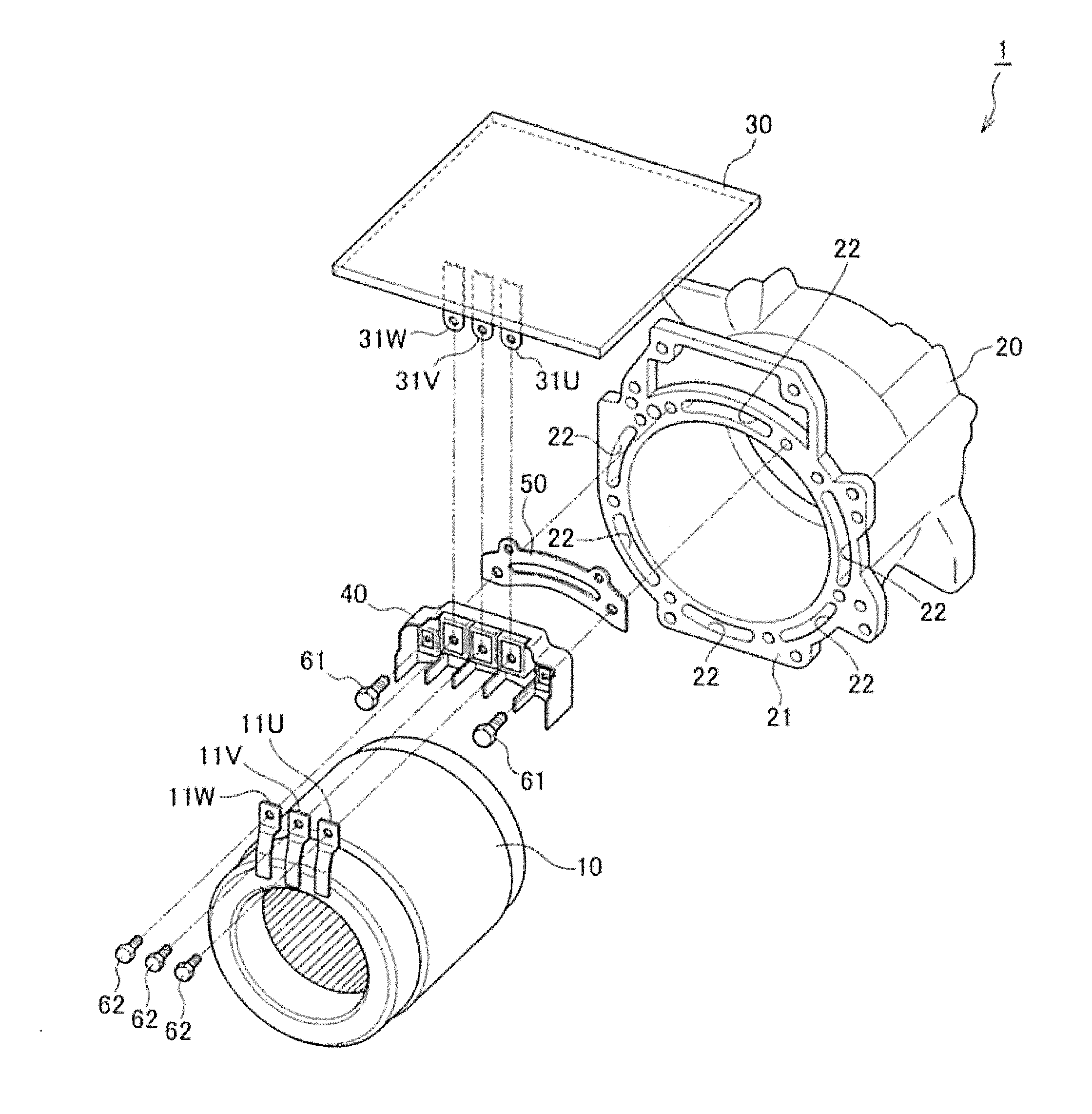
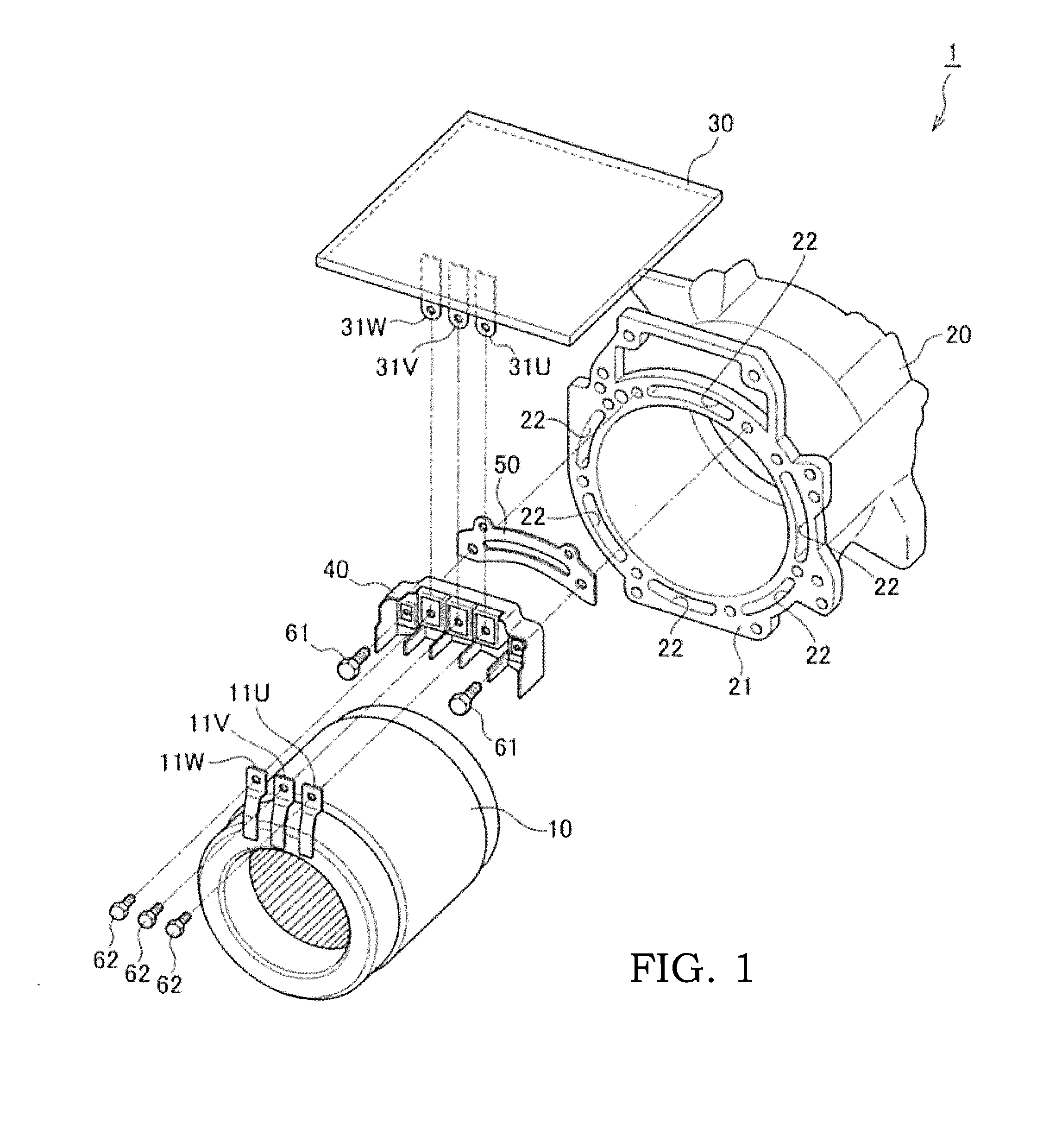
[0015]FIG. 1 is a perspective view illustrating major parts of a cooling structure for an electric motor according to the present invention.

[0016]A cooling structure 1 for an electric motor according to the present invention mainly includes a stator 10, a motor case 20, an inverter 30, and a terminal base 40.

[0017]The stator 10 is housed in the motor case 20 together with a rotor (not shown in the drawings). The stator 10 includes a U-phase motor power line 11U, a V-phase motor power line 11V, and a W-phase motor power line 11W. These motor power lines extend toward the inverter 30. In FIG. 1, since the inverter 30 is arranged above the motor case 20, these motor power lines extend upward. Further, as will be described later, the U-phase motor power line 11U is connected to a U-phase inverter power line 31U at the terminal base 40. The V-phase motor power line 11V is connected to a V-phase inverter power line 31V at the terminal base 40. The W-phase motor power line 11W is connected...

second embodiment

[0037]FIG. 4 is a view illustrating the cooling structure for the electric motor according to a second embodiment of the present invention, and is an enlarged view of the horizontal cross-section in the vicinity of the terminal base.

[0038]Hereinafter, the same reference numerals will be assigned to portions that perform the same functions as those explained above, and repetitive explanation will be omitted appropriately.

[0039]The terminal base body 42 according to the present embodiment includes a lid part 421 and a casting part 422.

[0040]The lid part 421 is made of metal. The lid part 421 is arranged so as to close the groove 22 of the motor case 20. An upper portion of the lid part 421 is formed so as to expand upward from a base thereof, and the casting part 422 is inserted into this wedge-shaped portion.

[0041]The casting part 422 casts the U-phase power line fixing portion 41U, the V-phase power line fixing portion 41V, the W-phase power line fixing portion 41W, and the wedge po...

third embodiment

[0043]FIG. 5 is a view illustrating the cooling structure for the electric motor according to a third embodiment of the present invention, and is an enlarged view of the horizontal cross-section in the vicinity of the terminal base.

[0044]The terminal base 40 according to the present embodiment includes an insulating member 44 sandwiched between the power line fixing portion 41 and the lid part 421. The insulating member 44 is a thin plate made of resin, for example.

[0045]In the configuration of the second embodiment, it is necessary to pour the resin for the casting part 422 even between the power line fixing portion 41 and the lid part 421. In order to secure flowability of the resin, a certain level of gap has to be provided between the power line fixing portion 41 and the lid part 421. Further, in order to secure strength of the resin between the power line fixing portion 41 and the lid part 421, it is necessary to provide a gap between the power line fixing portion 41 and the li...


PUM


Abstract

A cooling structure for an electric motor includes: a motor case that houses a stator and a rotor therein, a groove opened on an end surface in an axis direction of the rotor being formed in the motor case; a motor control circuit attached to the motor case; and a terminal base that closes the groove to constitute the groove as a cooling water passage through which cooling water can flow, the terminal base connecting a power line of the motor to a power line of the motor control circuit.

Description

TECHNICAL FIELD[0001]The present invention relates to a cooling structure for an electric motor.BACKGROUND ART[0002]In order to miniaturize a unit, a structure in which a motor control circuit (inverter) is integrated with an electric motor is known. In such a structure, since a power line for connecting the motor and the inverter is short, heat from a motor coil is easily conducted to the inverter via the power line. There is a possibility that a semiconductor element within the inverter is broken down in a case where the amount of conducted heat becomes larger.[0003]Therefore, JP2010-268633A discloses a structure for cooling a power line. Specifically, a terminal base that connects an inverter power line to a motor power line is connected to a cooler in which a water passage is incorporated via an L-shaped heat transfer member. One flat plate part (a first flat plate part) of the L-shaped heat transfer member is adhered and fixed to a surface of the cooler that is separated from t...

Claims


Application Information

Patent Timeline
IPC IPC(8): H02K9/193H02K5/22
CPCH02K5/225H02K9/193H02K11/33H02K5/203H01R9/24H02K5/20
Inventor OKANO, YOUJITANNO, TOSHIAKIMATSUZAKI, HIROKAZUOKUYAMA, TAKENARI
Owner NISSAN MOTOR CO LTD
Why Eureka
Try Eureka