
Power conversion device

Active Publication Date: 2015-08-27
TOYOTA JIDOSHA KK +1
View PDF9 Cites 10 Cited by
  • Summary
  • Abstract
  • Description
  • Claims
  • Application Information

AI Technical Summary

Benefits of technology

The patent describes a device that uses magnetic sensors to detect and measure magnetic fields. The invention allows for the use of multiple sensors on bus bars that are arranged in parallel, and the sensors can be positioned close to the outer shape of the device. The arrangement of the sensors allows for shorter circuit boards and reduces the width of the connector needed for power conversion. Additionally, the device includes a terminal block with fixed terminals and a terminal block with wider spaces between the terminals to accommodate larger connectors.

Problems solved by technology

However, if the spaces between the bus bars are wide, the sectional area of the space required for the bus bar group to pass through will be large, and a case in which the power conversion device is housed and the like will end up being large.

Method used


Image

  • Power conversion device
  • Power conversion device
  • Power conversion device

Examples


Embodiment Construction

[0028]The main characteristics of example embodiments described below will now be listed.

[0029](Characteristic 1) Three-phase current is supplied to a three-phase motor using three bus bars.

[0030](Characteristic 2) The power conversion device forms part of a circuit that supplies power from an onboard battery to an onboard motor.

[0031](Characteristic 3) A first flux concentration core and a second flux concentration core are stacked together with a magnetic insulating plate interposed therebetween.

[0032](Characteristic 4) The second flux concentration core and a third flux concentration core are stacked together with a magnetic insulating plate interposed therebetween.

[0033](Characteristic 5) A flux concentration core and a magnetic sensor are arranged on all of the three bus bars for the three phases. The bus bar group is a three-phase single system in which one flux concentration core and one magnetic sensor are arranged on each bus bar.

[0034](Characteristic 6) Two sets of three-p...


PUM


Abstract

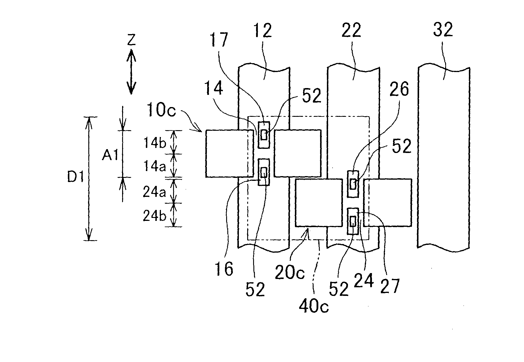
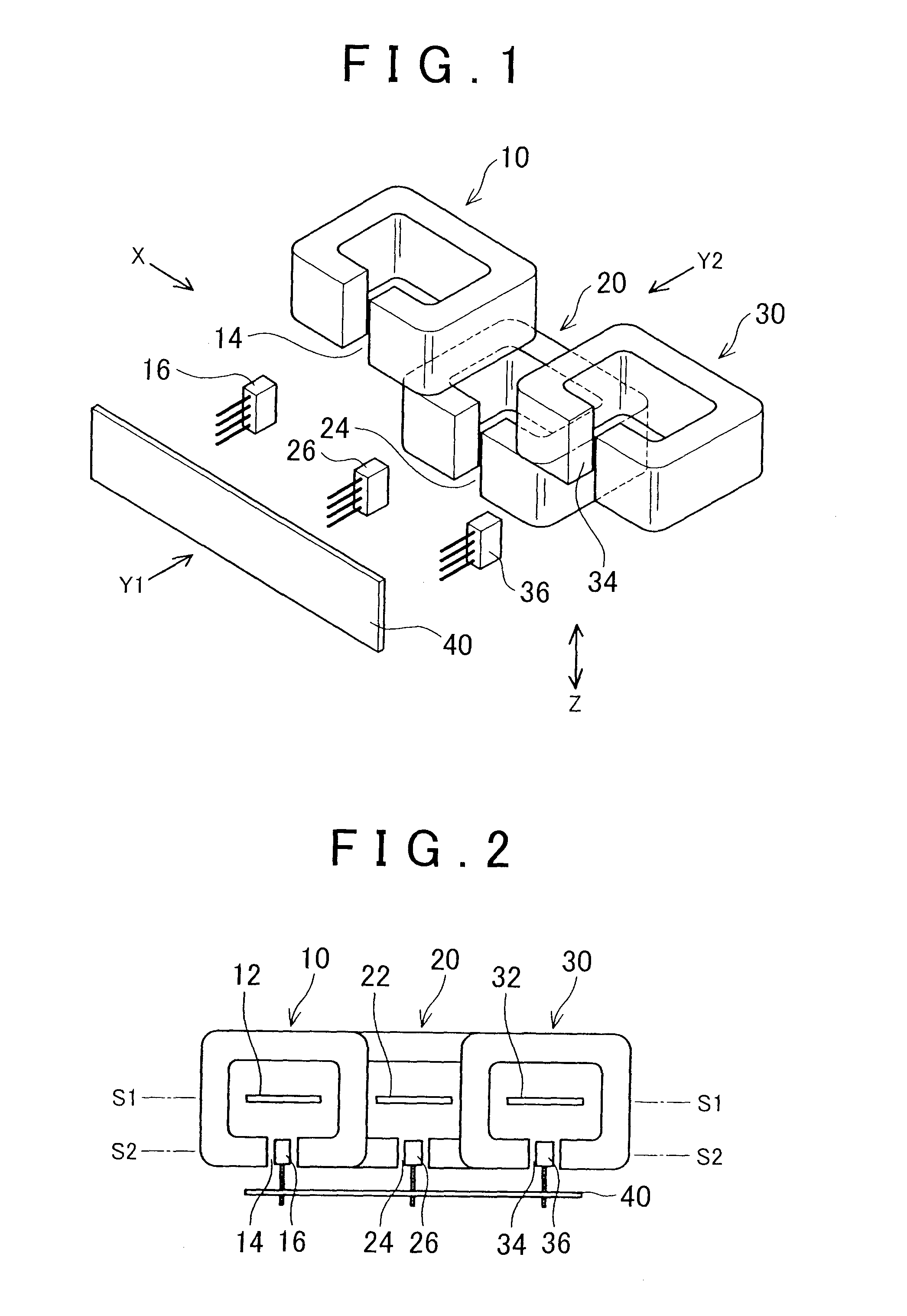
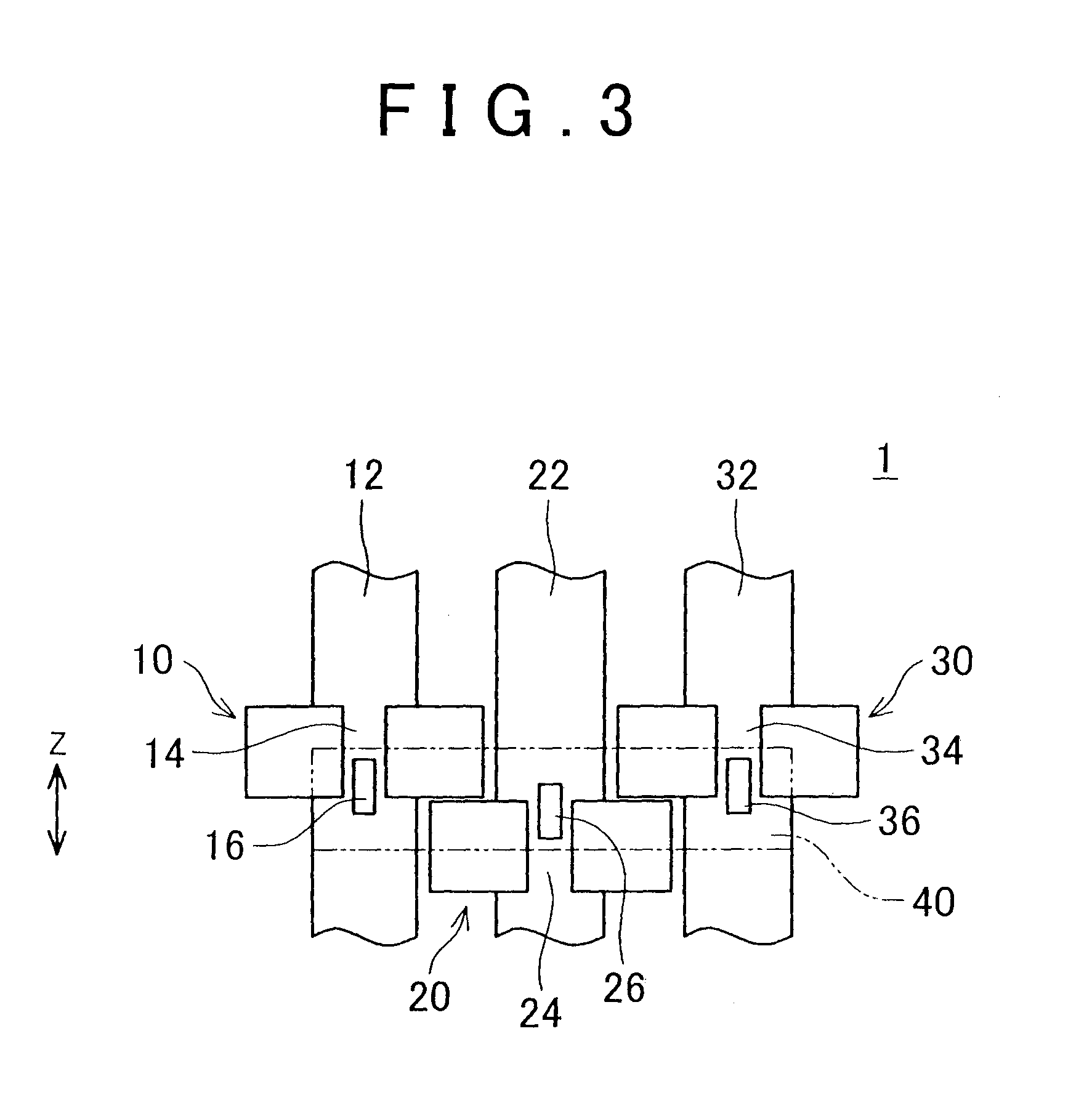
Flux concentration cores that encircle bus bars are arranged at different heights. When viewed from an extending direction (a Z-direction) of the bus bars, the first flux concentration core and the second flux concentration core that are adjacent to one another partially overlap each other, and the second flux concentration core and the third flux concentration core that are adjacent to each other partially overlap each other. Therefore, the flux concentration cores are able to be arranged around the bus bars even when the spaces between the bus bars are narrow.

Description

BACKGROUND OF THE INVENTION[0001]1. Field of the Invention[0002]The invention relates to a power conversion device that supplies power from a plurality of bus bars to an electrical device. More particularly, the invention relates to a power conversion device that detects conduction current values of the bus bars.[0003]2. Description of Related Art[0004]For example, three-phase current is supplied from three bus bars to a three-phase motor. When detecting the conduction current values of the bus bars, flux concentration cores 60, 70, and 80 are arranged around bus bars 62, 72, and 82, and magnetic sensors 66, 76, and 86 are arranged in gaps formed in the flux concentration cores, as shown in FIGS. 9A and 9B and described in Japanese Patent Application Publication No. 2011-053061 (JP 2011-053061 A).[0005]When arranging the flux concentration cores around the bus bars, the spaces between bus bars need to be wide. For example, there must be enough space between the first bus bar 62 and ...

Claims


Application Information

Patent Timeline
IPC IPC(8): H05K7/20H02G5/00H05K7/14
CPCH05K7/2089H02G5/00H05K7/14G01R15/207
Inventor SEO, YUSUKEHOTTA, YUTAKA
Owner TOYOTA JIDOSHA KK
Learn More