Optical member conveying device

a technology of optical member and conveying device, which is applied in the direction of optical elements, instruments, television systems, etc., can solve the problems of complicated structure of camera modules, achieve the effect of reducing the performance management value of a member, reducing the limitation of a camera module's size, and more accurate position of an optical axis

Inactive Publication Date: 2015-09-10
SHARP KK
View PDF5 Cites 18 Cited by
  • Summary
  • Abstract
  • Description
  • Claims
  • Application Information

AI Technical Summary

Benefits of technology

[0017]With the present invention, light is emitted from a top surface of a lens unit while the top surface of the lens unit is being sucked.
[0018]Accordingly, it is possible to carry out image recognition of an edge of a lens opening hole in accordance with a more accurate position of an optical axis. This can eliminate limitations on reducing a size of a camera module. Further, this increases (i) a region in which a lens barrel cylindrical section can be invisible when viewed from a back surface of a lens section and (ii) a region in which a resin can be applied to an edge of the back surface of the lens section. Even in a case where a tilt is occurring in the lens section, the tilt can be corrected before the lens section is mounted on the sensor section. This reduces a performance management value of a member. Accordingly, it is possible to reduce a cost and make full use of various products.

Problems solved by technology

Although the market has a strong demand for a reduction in size of the camera module, a structure of the camera module has become complicated, and thus a higher accuracy is required for positioning a lens with respect to an imaging element.

Method used


Image

  • Optical member conveying device
  • Optical member conveying device
  • Optical member conveying device

Examples


Embodiment Construction

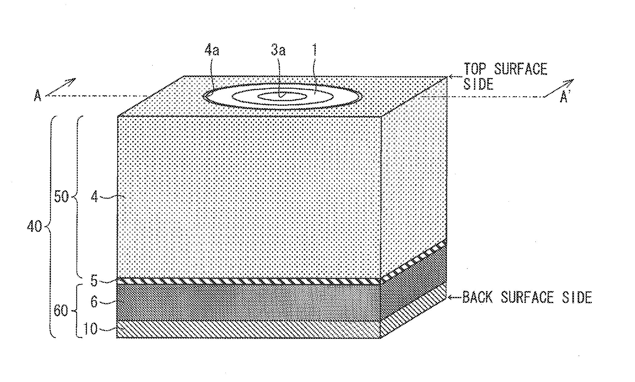
[0044]The following description will discuss, with reference to FIGS. 1 through 22, an embodiment of an optical member conveying device in accordance with the present invention. Note that before a discussion on the optical member conveying device of the present embodiment, the following description will discuss a camera module including a lens section which is to be conveyed by the optical member conveying device.

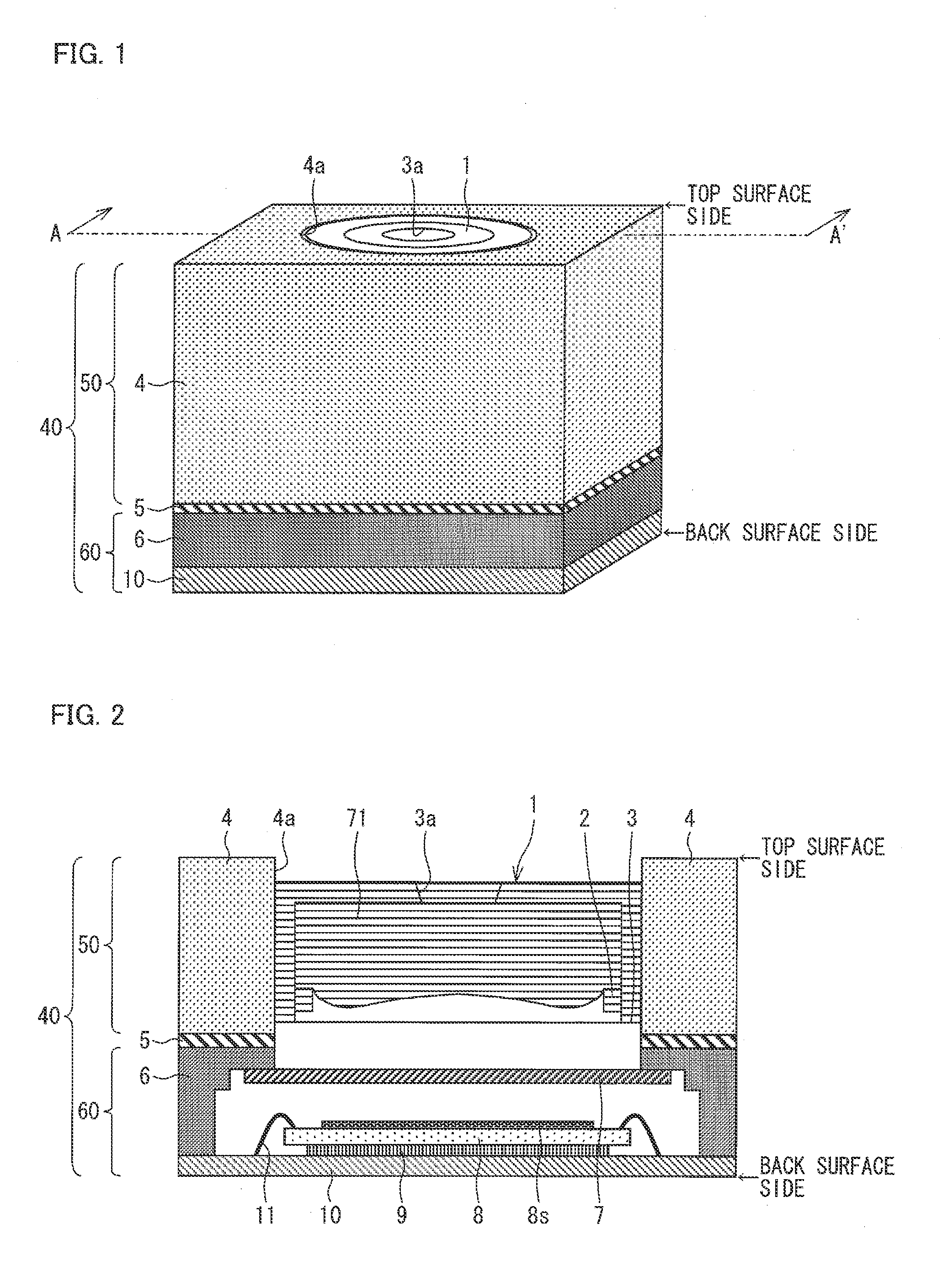
[0045]FIG. 1 is a perspective view illustrating a camera module 40 obtained by conveying a lens section, aligning the lens section with the sensor section, and then fixing the lens section to the sensor section by the optical member conveying device of the present embodiment. FIG. 2 is a cross-sectional view, taken along a cutting line A-A′ illustrated in FIG. 1, of the camera module 40.

[0046]The following description will first discuss a configuration of the camera module 40 and will then discuss a method of conveying the lens section and aligning the lens section with the...


PUM


Abstract

An optical member conveying device (90) of an embodiment of the present invention includes: a small LED illumination device (13) which (i) is included in a lens unit suction head (14) which adheres to a top surface of a lens section (50) and (ii) emits light from above the top surface of the lens section (50) toward an opening hole (3a) from which light enters, the opening hole (3a) being provided on the top surface of the lens section (50);
and a control section which controls the lens unit suction head (14) to carry out an alignment of the lens section (50) in accordance with a projection image obtained by projecting, by use of light emitted from the small LED illumination device (13), the opening hole (3a) on a side of a back surface of the lens section (50).

Description

TECHNICAL FIELD[0001]The present invention relates to an optical member conveying device for positioning a lens for a camera module which is to be mounted in an electronic device such as a mobile phone. The present invention particularly relates to an optical member conveying device which is capable of more accurately positioning a lens section including an imaging lens with respect to an imaging sensor section.BACKGROUND ART[0002]A camera module has been mounted in various electronic devices such as a mobile phone and a smartphone. Examples of camera modules encompass (i) a conventional camera module in which (a) no lens driving device is included and (b) a lens is held only by a holder and (ii) a camera module which uses a lens driving device to carry out an automatic focusing function and a camera shake correction function. These camera modules have been already distributed to the market. Examples of lens driving devices, i.e., actuators, encompass various types, such as a steppi...

Claims


Application Information

Patent Timeline
Patent Type & Authority Applications(United States)
IPC IPC(8): H04N5/225G02B7/02G01B11/27
CPCH04N5/2254G02B7/02G01B11/272G01B11/27H04N23/55G01B11/26G02B27/62H01L2224/48091H01L2224/73265H04N23/57H01L2924/00014
Inventor KAIOKA, SHINJIIKUNO, AKITOSHI
Owner SHARP KK
Why Eureka
Try Eureka