
Object Illumination in Hybrid Rasterization and Ray Traced 3-D Rendering

a hybrid rasterization and object illumination technology, applied in the field of 3d rendering systems, system architectures, methods, etc., can solve the problems that the processing tasks needed for ray tracing are not necessarily implementable on hardware, and the complexity of modern gpus can vary

Active Publication Date: 2015-09-17
IMAGINATION TECH LTD
View PDF10 Cites 55 Cited by
  • Summary
  • Abstract
  • Description
  • Claims
  • Application Information

AI Technical Summary

Benefits of technology

The patent describes a process for creating 3-D renderings of objects in a scene. The process involves determining the visible surfaces of pixels in each frame of a sequence of frames and shading those surfaces. The shading is done by sampling a texture that is mapped to the surface of an object and combining the results with existing data. The process also involves maintaining the texture by emitting rays and updating the data with the results of the sampling. The texture describes the ambient lighting conditions in the scene and can be prioritized based on its likelihood of being visible in a frame. The process can be implemented in graphics processors or systems on chip. The technical effect of the patent is to improve the accuracy and realism of 3-D renderings by accurately shading the surfaces of objects in the scene and maintaining the texture with each frame.

Problems solved by technology

Modern GPUs can range in complexity, with high performance GPUs having transistor budgets on the order of 4-6 billion transistors.
In ray tracing, control of rendering and pipeline flexibility to achieve a desired result were often more critical issues than maintaining a desired frame rate.
Also, some of the kinds of processing tasks needed for ray tracing are not necessarily implementable on hardware that is well-suited for rasterization.

Method used


Image

  • Object Illumination in Hybrid Rasterization and Ray Traced 3-D Rendering
  • Object Illumination in Hybrid Rasterization and Ray Traced 3-D Rendering
  • Object Illumination in Hybrid Rasterization and Ray Traced 3-D Rendering

Examples


Embodiment Construction

[0034]The following description is presented to enable a person of ordinary skill in the art to make and use various aspects of the inventions. Descriptions of specific techniques, implementations and applications are provided only as examples. Various modifications to the examples described herein may be apparent to those skilled in the art, and the general principles defined herein may be applied to other examples and applications without departing from the scope of the invention.

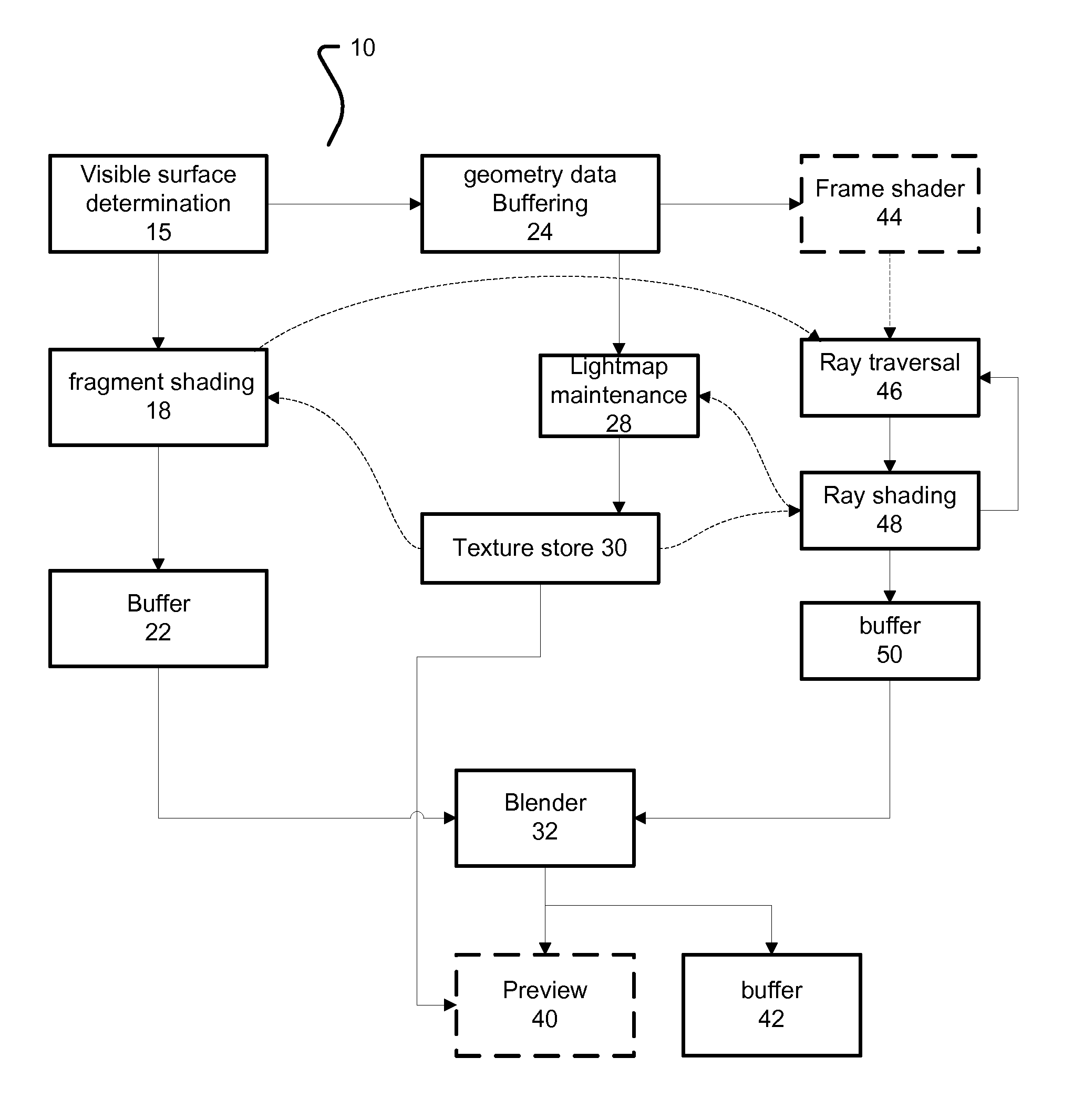
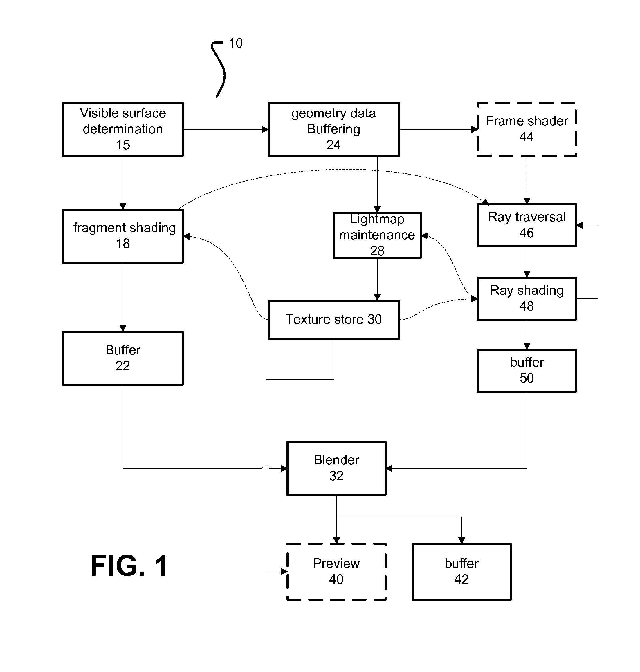
[0035]In general, systems and methods of rasterization have developed and been implemented largely separate from systems and methods of ray tracing, Rasterization has most often been used for real-time applications, and where constraints, such as computation or cost limits preclude usage of ray tracing. In contrast, ray tracing has more often been used in offline applications, where quality or physical correctness are valued more than frame rate, and / or computation cost. In one aspect, the disclosure rela...


PUM


Abstract

Rendering systems that can use combinations of rasterization rendering processes and ray tracing rendering processes are disclosed. In some implementations, these systems perform a rasterization pass to identify visible surfaces of pixels in an image. Some implementations may begin shading processes for visible surfaces, before the geometry is entirely processed, in which rays are emitted. Rays can be culled at various points during processing, based on determining whether the surface from which the ray was emitted is still visible. Rendering systems may implement rendering effects as disclosed.

Description

CROSS REFERENCE TO RELATED APPLICATIONS[0001]This application claims priority from U.S. Provisional App. No. 61 / 952,371, filed on Mar. 13, 2014, and entitled “Object Illumination in Hybrid Rasterization and Ray Traced 3-D Rendering”, which is incorporated by reference in its entirety herein for all purposes.BACKGROUND[0002]1. Field[0003]In one aspect, the disclosure generally relates to 3-D rendering systems, system architectures, and methods, and in a more particular aspect, the disclosure relates to systems, architectures, and methods for asynchronous and concurrent hybridized rendering, such as hybridized ray tracing and rasterization-based rendering.[0004]2. Description of Related Art[0005]Graphics Processing Units (GPUs) provide highly parallelized rasterization-based rendering hardware. A traditional graphics processing unit (GPU) used a fixed pipeline only for rendering polygons with texture maps and gradually evolved to a more flexible pipeline that allows programmable verte...

Claims


Application Information

Patent Timeline
IPC IPC(8): G06T15/04G06T15/06G06T15/80
CPCG06T15/04G06T2219/2012G06T15/06G06T15/80
Inventor FURSUND, JENSPETERSON, LUKE T.
Owner IMAGINATION TECH LTD
Learn More