
Apparatuses, methods, and systems for providing down force for an agricultural implement

a technology of agricultural implements and down force, applied in the field of agricultural implements, can solve the problems of difficult to maintain constant seed depth and other parameters, cumbersome changes in air pressure, and inability to adapt, and achieve the effect of reducing the amount of force needed

Active Publication Date: 2015-09-24
KINZE MFG INC
View PDF11 Cites 47 Cited by
  • Summary
  • Abstract
  • Description
  • Claims
  • Application Information

AI Technical Summary

Benefits of technology

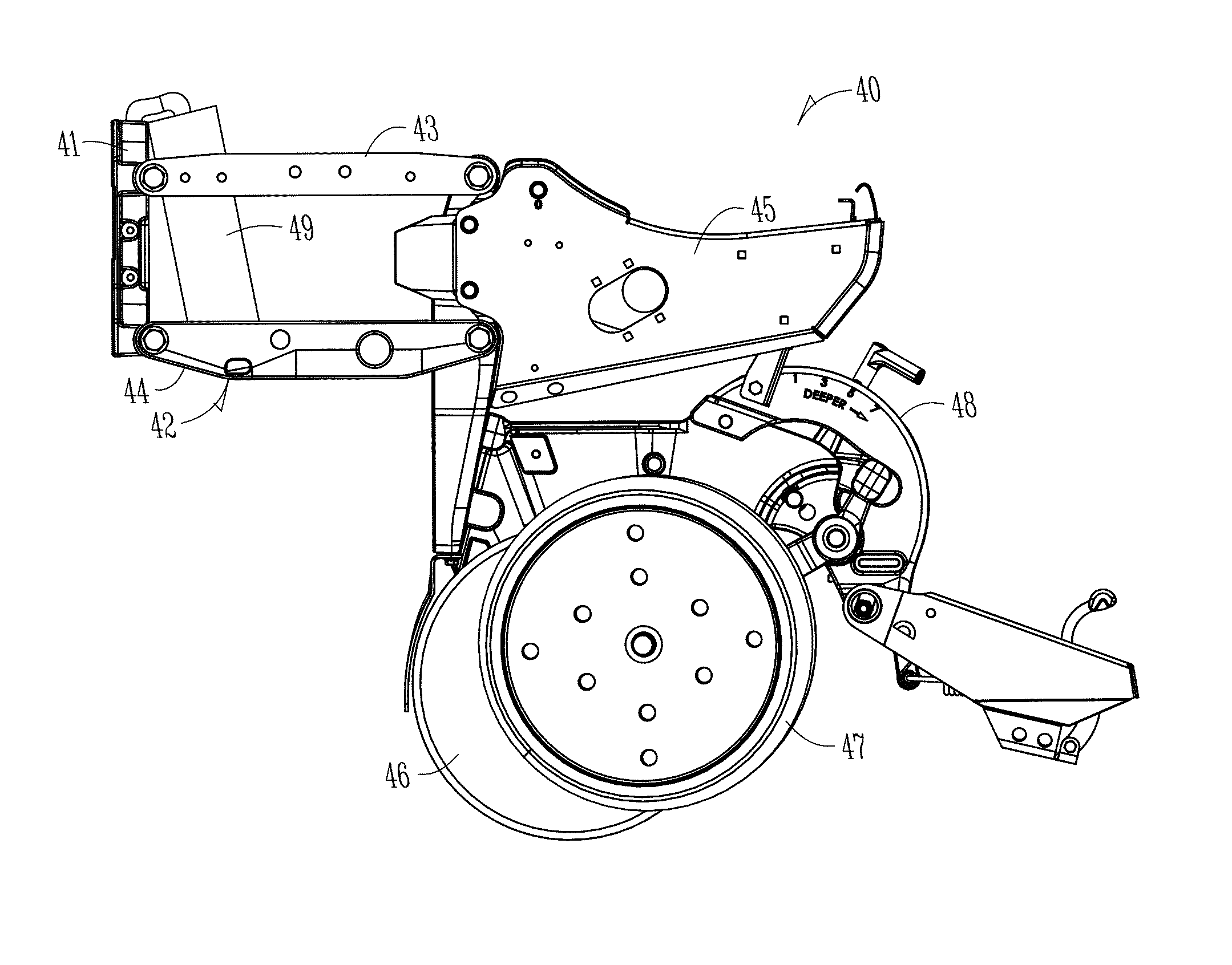
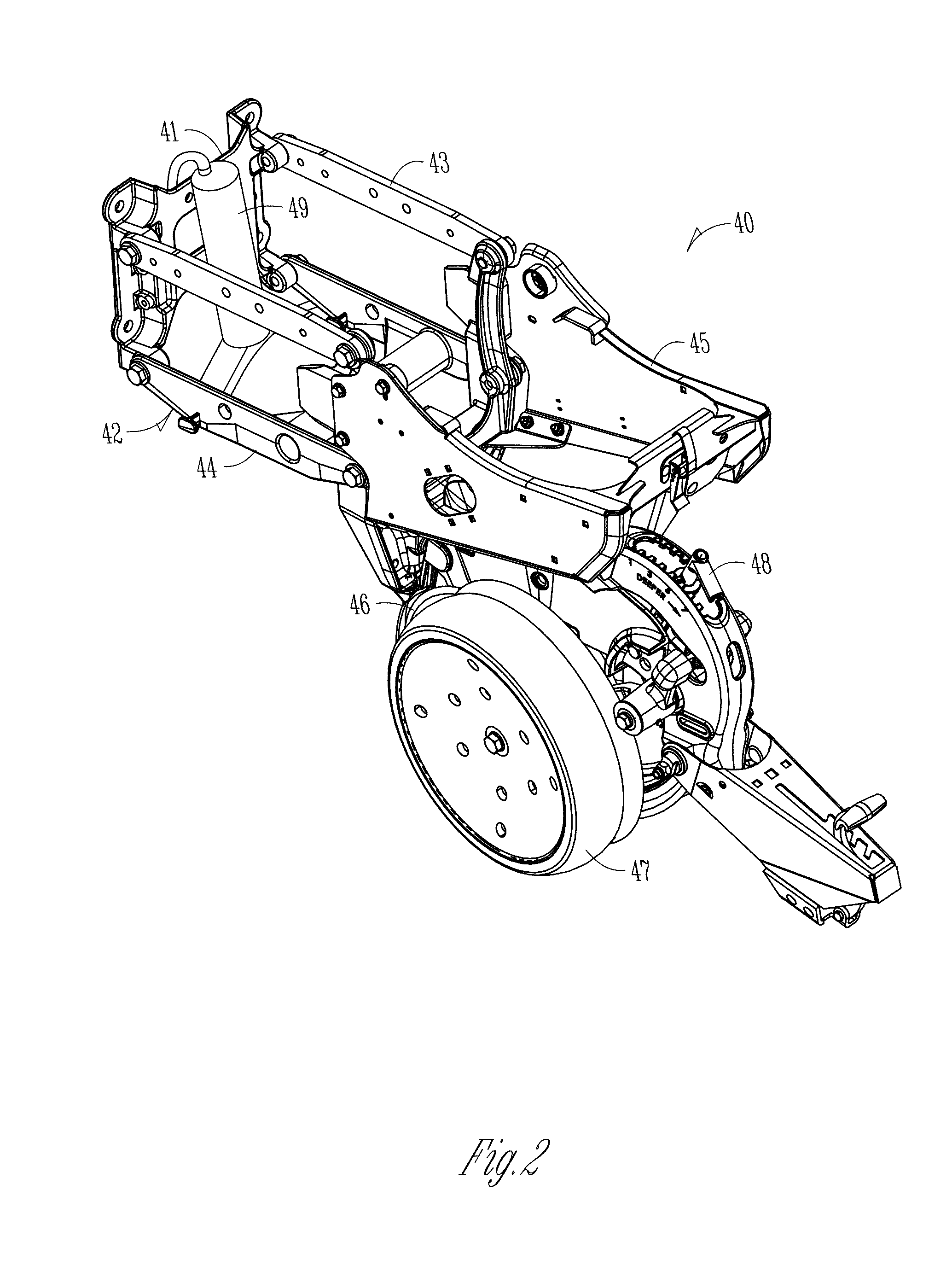
The invention provides an electric linear actuator to provide down force pressure at various locations of the row unit, a strut in place of a four bar linkage of a row unit, a connector for a seed meter, a row unit that is attached to a toolbar via a slider, and a moving actuator to the opening wheel of a row unit to reduce the amount of force needed for the wheel to penetrate the ground. These features improve the function and performance of the row unit.

Problems solved by technology

As the agricultural planter row unit travels across fields with variable soil types, soil moisture, residue levels and topography, it can be difficult to maintain constant seed depth and other parameters due to changing conditions which would ideally require varying the row unit down force pressure.
However due to the compressibility of air and the relatively large volumes required, changes in air pressure are very cumbersome and not adaptable to very fast change and response to in-cab controls on the go.
However, air bag systems typically do not allow for rapid change of the force being applied, because of the large volume of the air spring in relation to the cross section of the hose supplying the air.

Method used


Image

  • Apparatuses, methods, and systems for providing down force for an agricultural implement
  • Apparatuses, methods, and systems for providing down force for an agricultural implement
  • Apparatuses, methods, and systems for providing down force for an agricultural implement

Examples


Embodiment Construction

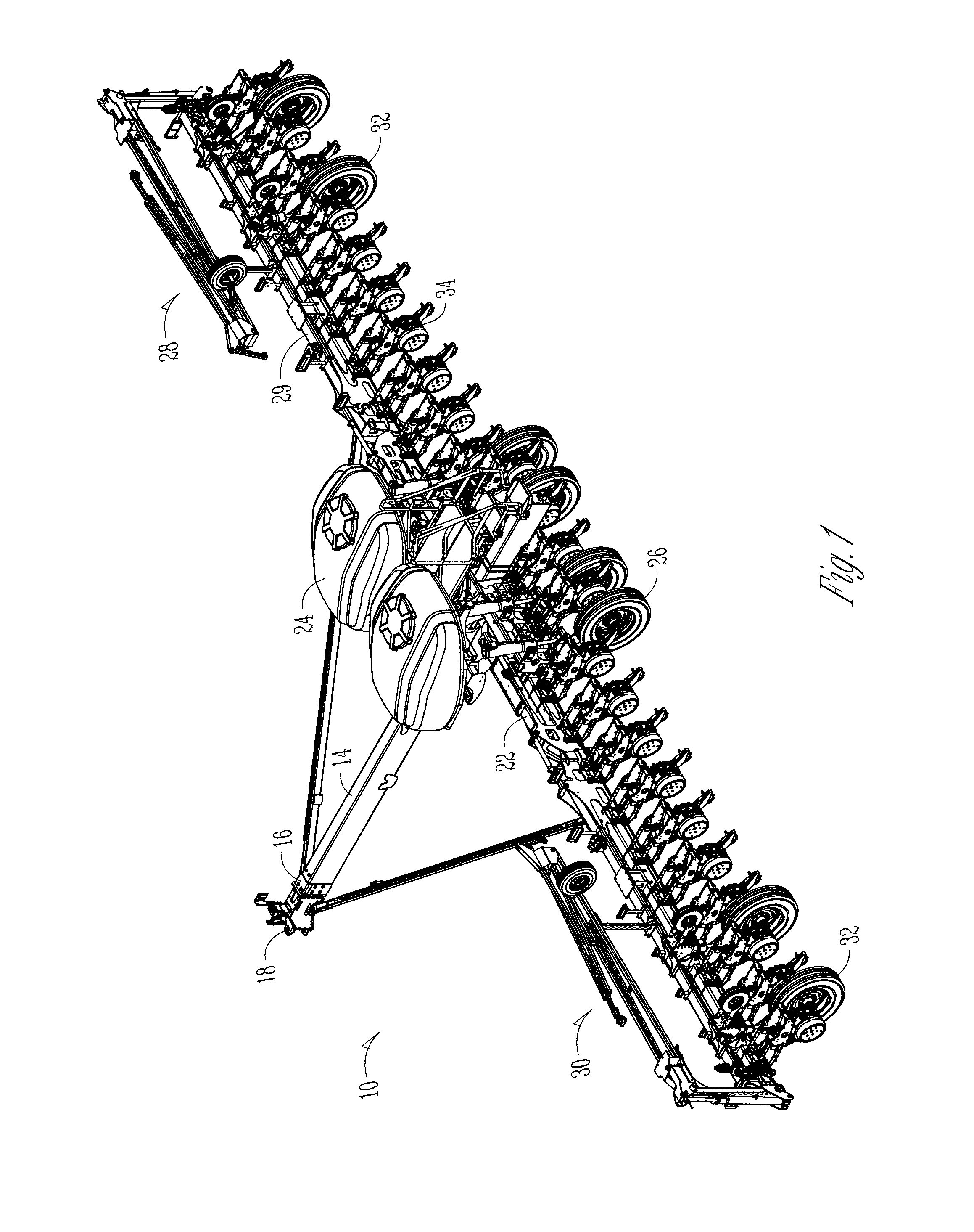
[0051]FIG. 1 shows an agricultural implement 10, in this case, an agricultural planter. The planter 10 is usually attached to and pulled by a tractor. However, it should be appreciated that other equipment and / or vehicles may move the implement 10. For purposes of the present disclosure, the implement 10 will be referred to as a planter.

[0052]The planter 10 includes a tongue 14 having a first end 16 and an opposite second end (not shown). The tongue 14 includes a hitch 18 at the first end 16, with the hitch 18 being connected to the tractor. At the opposite end of the tongue 14 is a central toolbar 22. The tongue 14 may be a telescoping tongue with components capable of being inserted into one another such that the implement 10 is a front folding style implement. However, the present invention is not to be limited to such front folding style implements and is to include any such implement for use in the agricultural industry.

[0053]As shown in FIG. 1, central hoppers 24 are positione...


PUM


Abstract

An agricultural planter includes systems, methods, and apparatus for providing down force pressure at row units of the planter. The row units may include an electric linear actuator connected to linkages of the row units to provide and maintain a down force pressure for the row unit. The linkage may also be removed and replaced with a strut or like mechanism to apply a direct down force pressure to components of the row unit. One or more sensors can be included to obtain information related to the ground to automatically adjust the amount of down force provided based upon a ground characteristic in order to maintain a substantially uniform furrow depth.

Description

CROSS-REFERENCE TO RELATED APPLICATIONS[0001]This application claims priority under 35 U.S.C. §119 to provisional application Ser. No. 61 / 968,820, filed Mar. 21, 2014, herein incorporated by reference in its entirety.FIELD OF THE INVENTION[0002]The invention relates generally to agricultural implements. More specifically, but not exclusively, the invention relates to systems, methods, and apparatus for providing down force pressure at row units of an agricultural planter.BACKGROUND OF THE INVENTION[0003]An agricultural row crop planter is a machine built for precisely distributing seed into the ground. The row crop planter generally includes a horizontal toolbar fixed to a hitch assembly for towing behind a tractor or other implement. Row units including seed meters are mounted to the toolbar. In different configurations, seed may be stored at individual hoppers on each row unit, or it may be maintained in a central hopper and delivered to the row units on an as needed basis. The ro...

Claims


Application Information

Patent Timeline
IPC IPC(8): A01B63/32A01B63/28A01B61/04A01C5/06A01B49/06
CPCA01B63/32A01C5/062A01B63/28A01B61/044A01B49/06A01C7/203A01C5/064A01C7/205A01C7/20
Inventor ACHEN, COURTNEY N.BACHMAN, MARVINSCHILDROTH, RHETTROLFFS, MERLANMYERS, MICHAEL J.KOLLMAN, JOHNMULHERIN, JOHN P.
Owner KINZE MFG INC
Learn More