
Golf tee gadget and configuration

a golf tee and gadget technology, applied in the field of golf tee gadgets and configuration, can solve the problems of slowing down the golf club before hitting the golf ball, broken tees, and broken tees on conventional golf courses, so as to improve the accuracy of golf strikes, improve the golfer's swing alignment, and reduce the effect of undesirable forces

Inactive Publication Date: 2015-09-24
HASSANLOU RAYMOND
View PDF23 Cites 0 Cited by
  • Summary
  • Abstract
  • Description
  • Claims
  • Application Information

AI Technical Summary

Benefits of technology

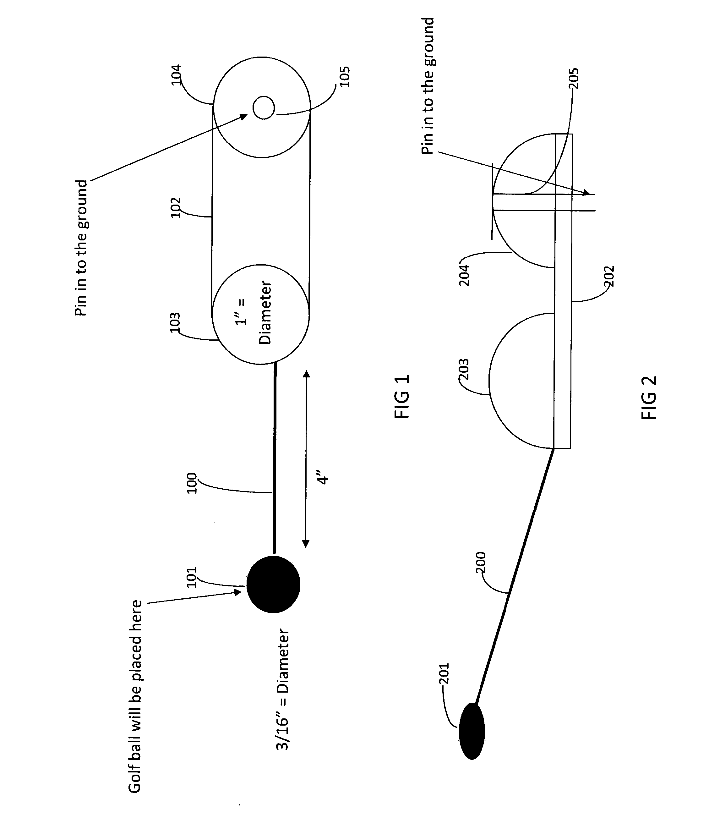
The present invention is a golf tee gadget and configuration that aims to improve golfers' swing alignment and reduce littering on the golf course. The invention includes a tee that does not stand upright but lies flat on the ground and includes a long pin that extends at an angle from the flat part. The golf ball is placed on the tee at an elevated position compared to the stem, which prevents direct contact with the stem during the swing. The invention also includes two golf balls placed on either end of a flat plate, which forces the player's body to align more correctly behind the ball and results in more accurate swings and shots. This arrangement helps the player to align and direct their swings and shots. Overall, the invention aims to improve the golfer's strike accuracy and reduce littering on the golf course.

Problems solved by technology

Normally, teeing the ball is allowed only on the first shot of a hole, called the tee shot, and is illegal for any other shot; however, local or seasonal rules may allow or require teeing for other shots as well, e.g., under “winter rules” to protect the turf when it is unusually vulnerable.
A drawback of the conventional golf tees is the pollution caused by them as a typical hit results in a broken Tee.
As a result, conventional golf courses are usually littered with broken tees around the teeing grounds.
Another problem with the conventional golf tee gadgets is that they interfere with the swing path of the golf club, thus slowing down the golf club prior to striking the golf ball.
Yet another problem with the conventional golf tee gadgets is caused by an alignment failure.
The alignment failure is significant because even a slight twist of the club due to the influence of the golf tee would cause significant alteration in the intended landing location of the ball.
Conventional golf tees do not provide satisfactory suspension mechanism for the golf ball that is substantially unhindered by physical contact with a golf tee, prior to impact by a golf club.
Several adverse consequences can result from the interaction of a conventional golf tee and golf club.
This, in turn, causes “pushes back” by the dirt on the below ground portion of the tee.
This force is then transmitted through the stem of the tee and may affect golfer's swing, alter the swing path, reduce club head speed, or produce other undesirable effects.
An additional issue facing golfers is the ability to reliably set the height of the golf ball that is being hit.
However, due to the inherent error in such an arrangement, golfer may frequently hit the golf ball from varying heights on different strokes during a golf round, which are at variance from each other.
The inability to reliably set the golf ball at a certain height can itself result in inconsistent play and shots.
Another problem with conventional golf tees is that they fail to provide player with an proper alignment to allow golfer to optimally strike the golf ball with the golf club swing.
As a result, golfer has no consistent linear frame of reference by which to aim his or her stroke.
This, in turn, can lead to a greater percentage of errant golf shots.

Method used


Image

  • Golf tee gadget and configuration
  • Golf tee gadget and configuration

Examples


Embodiment Construction

)

[0017]A golf tee gadget and configuration includes a stem with one end connected to a surface on which a golf ball can be held, and a flat plate connected to the other end of the stem, with the stem being connected to the flat plate at an angle. The flat plate includes one golf ball at each end. Viewed from a direct top position, the two golf balls and the stem surface are positioned along the same horizontal line that connects the golf ball centers and the center of the stem surface. The flat plate is pinned to the ground via a pin. The pin is located at an end of the plate that is farther from the stem and is inserted from the top of the golf ball and extends through the middle of the golf ball. The pin is made of a non-breakable flexible material. The flat plate length is shorter than the length of the stem.

[0018]Details of the present invention relating to various exemplary embodiments will now be described by reference to the drawings.

[0019]FIG. 1 shows the inventive golf tee ...


PUM


Abstract

A golf tee gadget and configuration includes a stem with one end connected to a surface on which a golf ball can be held, and a flat plate connected to the other end of the stem, with the stem being connected to the flat plate at an angle. The flat plate includes one golf ball at each end. When the stem is in a flattened position, the two golf balls and the stem surface are positioned along the same horizontal line that connects the golf ball centers and the center of the stem surface. The flat plate is pinned to the ground via a pin. The pin is located at an end of the plate that is farther from the stem and is inserted from the top of the golf ball and extends through the middle of the golf ball. The pin is made of a non-breakable flexible material. The flat plate length is shorter than the length of the stem.

Description

BACKGROUND OF THE INVENTION[0001]A tee is a stand that is typically used to support a stationary ball. In golf, a tee is normally used for the first stroke of each hole. The area from which this first stroke is hit is known as the teeing ground. Normally, teeing the ball is allowed only on the first shot of a hole, called the tee shot, and is illegal for any other shot; however, local or seasonal rules may allow or require teeing for other shots as well, e.g., under “winter rules” to protect the turf when it is unusually vulnerable. Teeing gives a considerable advantage for drive shots, so it is normally done whenever allowed. However, a player may elect to play his / her tee shot without a tee. This typically gives the shot a lower trajectory1.[0002]A conventional golf tee includes a conical spike that is pinned into the ground and a slightly concaved head portion on which golf ball is placed. The standard golf tee pin is made of wood or hard plastic.[0003]A drawback of the conventio...

Claims


Application Information

Patent Timeline
Patent Type & Authority Applications(United States)
IPC IPC(8): A63B57/00
CPCA63B2057/0025A63B57/005A63B57/12A63B2071/024
Inventor HASSANLOU, RAYMOND
Owner HASSANLOU RAYMOND
Learn More