Light directing film

a technology of light directing film and optical substrate, which is applied in the direction of lighting and heating apparatus, instruments, mechanical equipment, etc., can solve the problems of reducing the efficiency of hybrid brightness enhancement film in directing light, creating undesirable visible artifacts in display images, and relatively complex structures requiring relatively higher manufacturing costs. achieve the effect of enhancing luminance or brightness and reducing interference fringes

Active Publication Date: 2015-09-24
UBRIGHT OPTRONICS CORP
View PDF5 Cites 2 Cited by
  • Summary
  • Abstract
  • Description
  • Claims
  • Application Information

AI Technical Summary

Benefits of technology

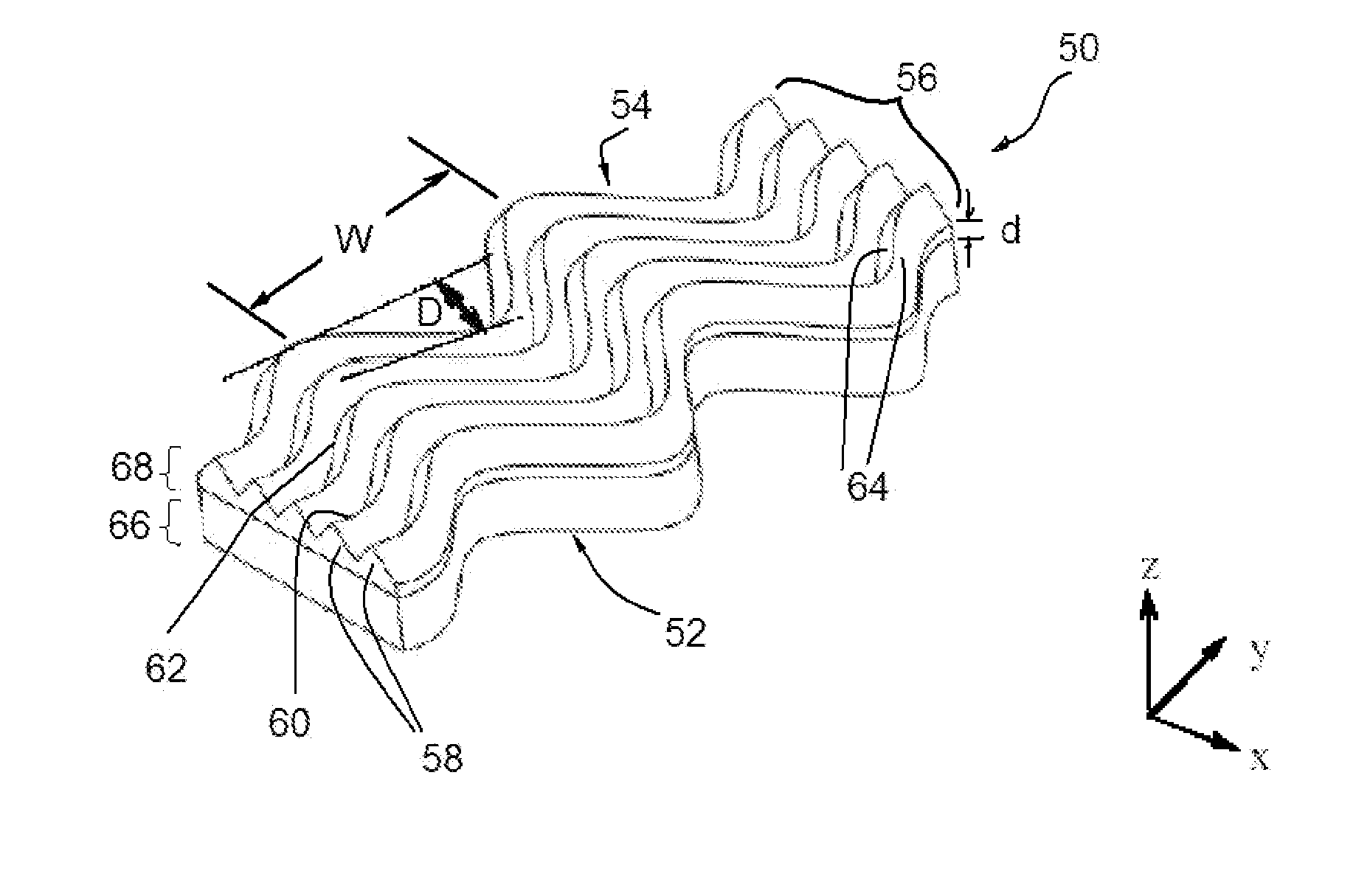
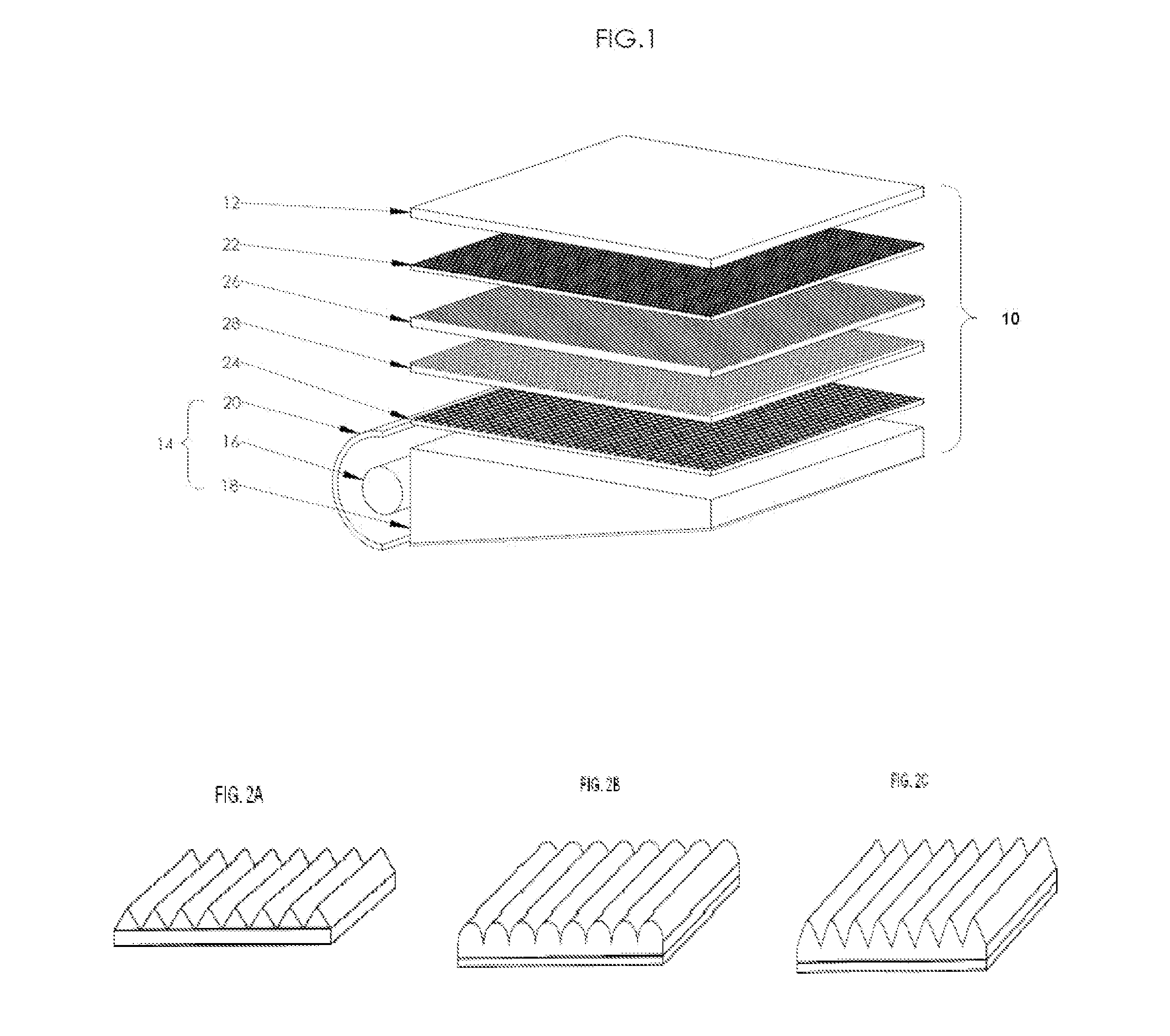
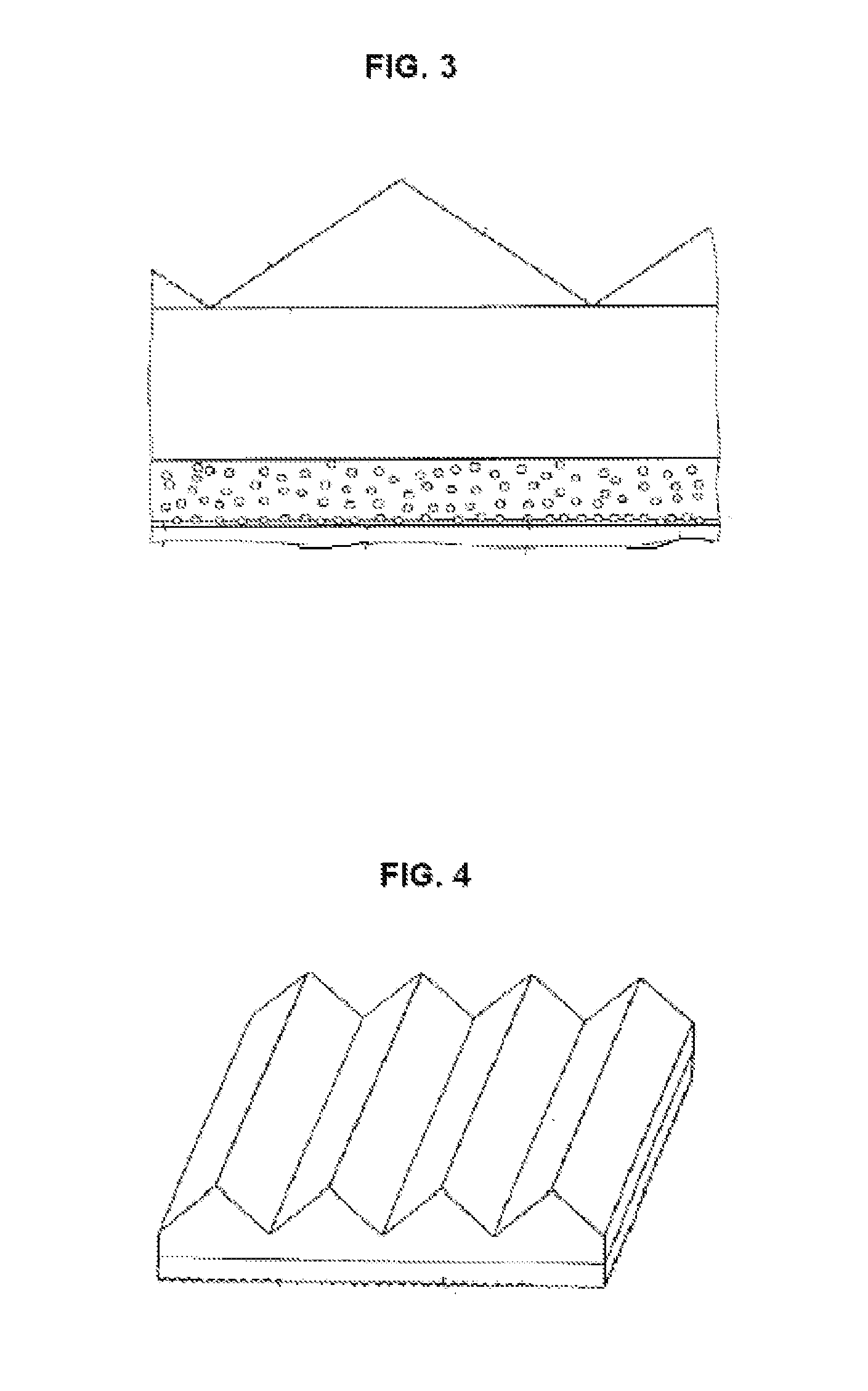
[0017]The present invention is directed to an optical substrate that possesses a structured surface that enhances luminance or brightness and reduces interference fringes in the display images. In one aspect of the present invention, the optical substrate is in the form of a film, sheet, plate, and the like, which may be flexible or rigid, having a structured light output surface that comprises rows of laterally arranged snaking, wavy or meandering longitudinal prism structures. In one embodiment, the prism structures at the light output surface may be viewed as comprising rows of laterally meandering longitudinal prisms and / or sections of continuous curved segments (i.e., sections with a curve in a particular direction, or generally C-shaped curve sections) coupled end-to-end to form the overall meandering longitudinal prism structures. In one embodiment, the laterally meandering rows of longitudinal prism structures are arranged in parallel laterally (side-by-side), defining parallel peaks and valleys (a facet is defined between each adjacent peak and valley). In one embodiment, the lateral waviness is regular with a constant or variable wavelength and / or wave amplitude (or extent of lateral deformation). The lateral waviness may generally follow a sinusoidal profile, or other curved profile. In another embodiment, the lateral waviness may be of random wavelength and / or wave amplitude. In one embodiment, the peaks are of constant or similar height and / or the valleys are of constant or similar depth, across the plane of the substrate. The pitch between adjacent peaks / valleys may be constant across a particular cross-sectional plane. In one embodiment, the optical substrate includes a non-structured, smooth, planar, or glossy light input surface. In one embodiment, the light output surface and the light input surface are generally parallel to each other in the overall optical substrate structure (i.e., do not form an overall substrate structure that is generally tapered).

Problems solved by technology

When the brightness enhancement films are used in LCDs, with the glossy bottom surface of a brightness enhancement film above the structured surface of another brightness enhancement film, it has been experienced that the optical interaction between the glossy surface of top enhancement film and the structured surface and / or glossy surface of the lower brightness enhancement film creates undesirable visible artifacts in the display image in the form of interference fringes (i.e., bright and dark repeated patterns) that are observable in the display image.
However, the above-mentioned hybrid brightness enhancement films involve relatively complex structures requiring relatively higher manufacturing costs.
Moreover, the hybrid brightness enhancement films are also less effective in directing light within the desirable viewing angle.
Furthermore, in the absence of a separate top diffuser film between the structured surface of the top hybrid brightness enhancement film and the underside of the LC module, undesirable interference fringes appearing as bright and dark patterns may be generated.

Method used


Image

  • Light directing film
  • Light directing film
  • Light directing film

Examples


Embodiment Construction

[0041]The present description is of the best presently contemplated mode of carrying out the invention. This invention has been described herein in reference to various embodiments and drawings. This description is made for the purpose of illustrating the general principles of the invention and should not be taken in a limiting sense. It will be appreciated by those skilled in the art that variations and improvements may be accomplished in view of these teachings without deviating from the scope and spirit of the invention. The scope of the invention is best determined by referenced to the appended claims.

[0042]The present invention is directed to an optical substrate that possesses a structured surface that enhances luminance or brightness and reduces interference fringes in the display images. In one aspect of the present invention, the optical substrate is in the form of a film, sheet, plate, and the like, which may be flexible or rigid, having a structured light output surface t...


PUM


Abstract

The present invention discloses a light directing film comprising a first structured major surface, a second major surface opposite to the first structured major surface, wherein the first structured major surface comprises a first prism element and a second prism element meandering in a wary manner.

Description

CROSS-REFERENCE TO RELATED APPLICATIONS[0001]This application is a continuation-in-part of U.S. patent application Ser. No. 14 / 171,645 filed on Feb. 3, 2014, which is a continuation of U.S. patent application Ser. No. 12 / 854,815 filed on Aug. 11, 2010, now U.S. Pat. No. 8,641,259, which claims (a) priority of U.S. provisional application Ser. No. 61 / 233,040 filed on Aug. 11, 2009, and is: (b) a continuation-in-part of U.S. patent application Ser. No. 11 / 825,139 filed on Jul. 2, 2007, now U.S. Pat. No. 7,883,647, which claims priority of U.S. provisional application Ser. No. 60 / 818,044 filed on Jun. 30, 2006; (c) a continuation-in-part of U.S. patent application Ser. No. 12 / 455,021 filed on May 26, 2009, now U.S. Pat. No. 8,899,768, which claims priority of U.S. provisional application Ser. No. 61 / 128,813 filed on May 23, 2008; (d) a continuation-in-part of U.S. patent application Ser. No. 12 / 590,855 filed on Nov. 12, 2009, now U.S. Pat. No. 8,517,573, which is a continuation of U.S....

Claims


Application Information

Patent Timeline
Patent Type & Authority Applications(United States)
IPC IPC(8): G02B5/02F21V8/00
CPCG02B5/0231G02B6/0058G02B6/0053G02B5/045
Inventor WANG, KONG-HUAYANG, CHING-ANPAN, HAN-TSUNG
Owner UBRIGHT OPTRONICS CORP
Why Eureka
Try Eureka