Techniques for emergency detection and emergency alert messaging

Active Publication Date: 2015-09-24
ZHANG JACK KE
View PDF3 Cites 73 Cited by
  • Summary
  • Abstract
  • Description
  • Claims
  • Application Information

AI Technical Summary

Benefits of technology

[0008]This apparatus can also be configured to monitor various vital signs of the wearer via one or more sensors. The apparatus can includes such sensors, for example but without limitation, a blood-oxygen level sensor(s), hear rate monitor(s), blood pressure monitor(s), glucose monitor(s), pedometer(s), thermometer(s), and the like. The sensors can provide readings used to provide wellness monitoring as described herein.
[0009]This disclosure also describes systems, methods and computer-program products in which the inventive elements, techniques and process herein disclosed may be embodied. The system, method and computer-program product may be for monitoring a person wearing a device, the device having multiple sensors disposed therein. The system and computer-program product may be configured to perform certain of the following processes which also may characterize t

Problems solved by technology

Certain individuals may be vulnerable to emergency medical situations resulting from unexpected falls, fainting, collapse, drops or spikes in blood pressure, oxygen saturation, heart rate, and other health related situations.
Most of these devices are worn by an individual at risk of falling.
However, detecting falls can be a complicated problem because data registered during a fall may be affected by noise or may be similar to data generated when the wearer performs certain commonplace actions.
For these reasons, conventional fall detectors are highly susceptible to failures when a fall occurs, as well as false-positive fall detections.
In addition, while devices for monitoring a wearer's vit

Method used


Image

  • Techniques for emergency detection and emergency alert messaging
  • Techniques for emergency detection and emergency alert messaging
  • Techniques for emergency detection and emergency alert messaging

Examples


Embodiment Construction

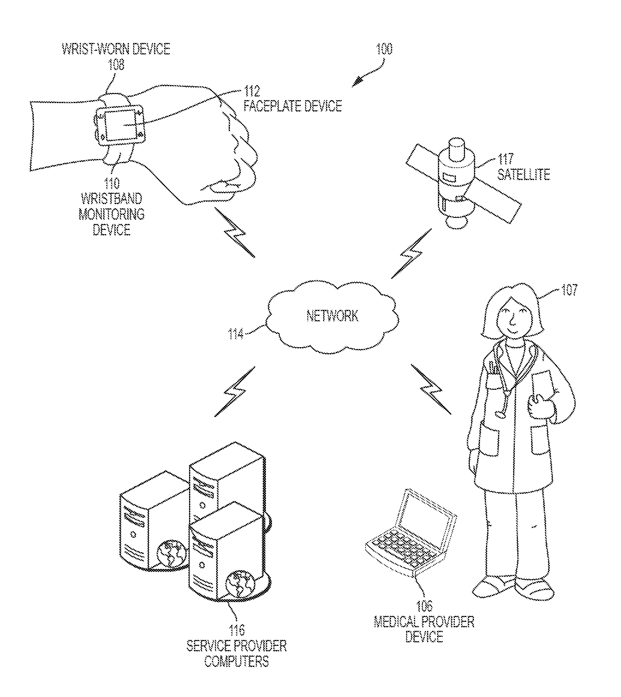
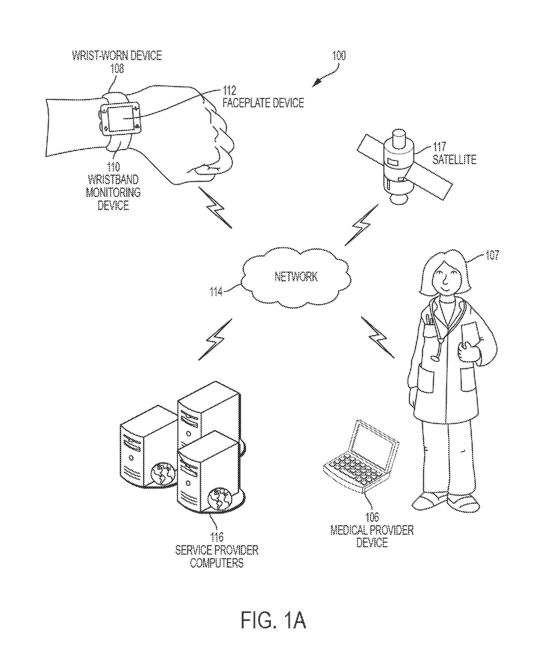
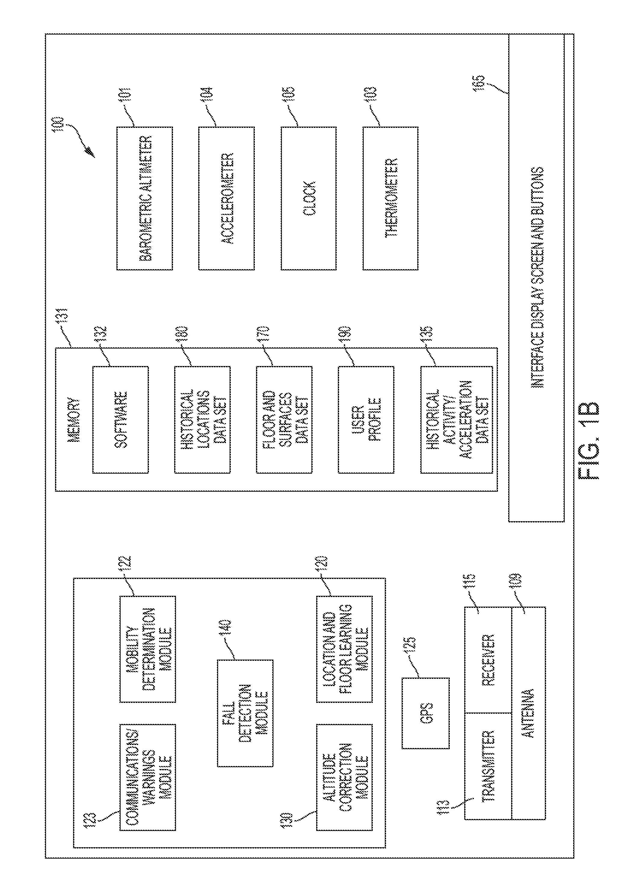
[0029]This disclosure describes an emergency detection and monitoring device configured to be worn on the human body (e.g., a watch). The monitoring device includes sensory, communications, processing and software components that provide functionality for executing any number of the techniques, processes or methods (hereinafter the term “disclosed procedures” will refer to the techniques, processes and methods) which are described in this disclosure. The disclosed features enable the monitoring device to detect an emergency situation affecting the wearer of the monitoring device and inform emergency medical personnel when an emergency situation is detected.

[0030]The monitoring device may be configured as a wrist-worn device or other similar accessory suitable for attachment on the user's arm or at any other location on the body. The monitoring device includes sensors and wireless communication interfaces that gather or receive data used by the monitoring device to monitor the wearer...


PUM


Abstract

A method, apparatus, and/or system for monitoring a user and transmitting an emergency notification is disclosed. The apparatus can monitor a user's overall wellness and adherence to a therapy regimen. The apparatus can also detect a variety of emergency situations affecting the user. For example, the apparatus can detect a fall affecting the user, the activation of an emergency indicator by the user, or an emergency based on vital signs and the overall wellness of the user. The apparatus can generate and transmit an alert notification in response to determining an emergency is affecting the user. The apparatus can select the form of the alert and the network on which to transmit the alert. The apparatus can determine the form of the alert and the network based on the severity of the emergency and the strength of the networks available to the apparatus. The form of the alert and the transmission network selected can optimize the likelihood of the alert notification being successfully transmitted.

Description

CROSS REFERENCE TO RELATED APPLICATIONS[0001]The present application is a continuation-in-part of U.S. patent application Ser. No. 14 / 591,782, filed Jan. 7, 2015, which is a continuation of U.S. patent application Ser. No. 14 / 218,888, filed Mar. 18, 2014, now issued as U.S. Pat. No. 8,952,818 on Feb. 10, 2015, and is related to PCT Application No. ______ (Attorney Docket No. 96339-939181) filed on Mar. 18, 2015, each of which is incorporated herein by reference in its entirety.BACKGROUND[0002]Aspects of the disclosure relate to an emergency detection device with wireless alert capabilities and location reporting.[0003]Certain individuals may be vulnerable to emergency medical situations resulting from unexpected falls, fainting, collapse, drops or spikes in blood pressure, oxygen saturation, heart rate, and other health related situations. These individuals include the elderly, medicating patients and other individuals who suffer from heart conditions, epilepsy or other such medical...

Claims


Application Information

Patent Timeline
IPC IPC(8): G08B21/04A61B5/00
CPCG08B21/0438G08B21/0446G08B21/0453A61B5/0015A61B5/0022A61B5/1117A61B5/746G08B21/043G08B25/004G08B25/016G08B29/16G08B29/185G08B29/188G16H40/67Y02A90/10
Inventor ZHANG, JACK KE
Owner ZHANG JACK KE
Why Eureka
Try Eureka