
Precoding for single transmission streams in multiple antenna systems

a transmission stream and antenna technology, applied in the field of wireless communications, can solve problems such as inter-symbol interference, difficult multipath resolution, and constructive and destructive addition at the receiver

Active Publication Date: 2015-09-24
CENT OF EXCELLENCE & WIRELESS TECH
View PDF0 Cites 45 Cited by
  • Summary
  • Abstract
  • Description
  • Claims
  • Application Information

AI Technical Summary

Benefits of technology

The invention provides a method and system for transmitting signals from multiple antennas using a single stream transmission. The method involves dividing the signal into a plurality of subcarriers, each with a unique complex weight that is specific to the antenna. The complex weights are determined based on the time and frequency indices of the subcarriers. The signals are then transmitted simultaneously from all antennas using the assigned complex weights. The method also includes a method for estimating channel state information and interference covariance estimation. The invention provides a more efficient way to transmit signals over multiple antennas and improves the quality of the received signal.

Problems solved by technology

This results in the superposition of different multi-path signals, adding constructively and destructively at the receiver.
Resolving the multipaths becomes difficult in system operating at very high carrier frequencies.
The un-resolvable multiple paths contribute to fading and the resolvable multiple paths lead to inter-symbol interference (ISI).
In conventional STBC / SFBC schemes, distinct pilot tones are transmitted on different antennas which results in a high pilot overhead.
STBC / SFBC schemes also require higher complexity during implementation.
In ISI channels, the performance of Cyclic Delay Diversity (CDD) is generally poor.

Method used


Image

  • Precoding for single transmission streams in multiple antenna systems
  • Precoding for single transmission streams in multiple antenna systems
  • Precoding for single transmission streams in multiple antenna systems

Examples


Embodiment Construction

[0048]The embodiments herein and the various features and advantageous details thereof are explained more fully with reference to the non-limiting embodiments that are illustrated in the accompanying drawings and detailed in the following description. Descriptions of well-known components and processing techniques are omitted so as to not unnecessarily obscure the embodiments herein. The examples used herein are intended merely to facilitate an understanding of ways in which the embodiments herein may be practiced and to further enable those of skill in the art to practice the embodiments herein. Accordingly, the examples should not be construed as limiting the scope of the embodiments herein.

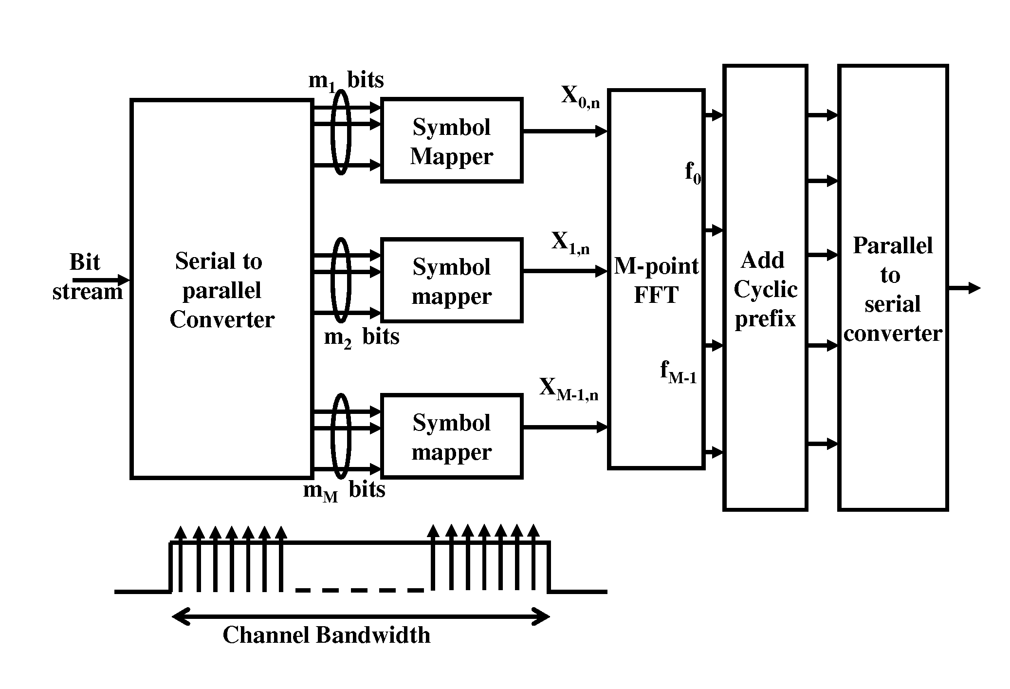
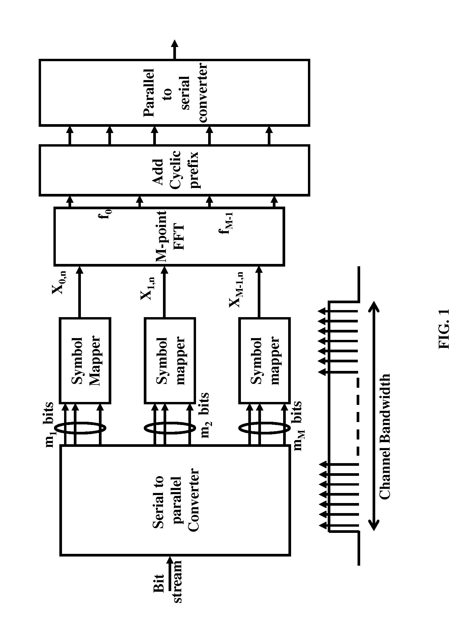
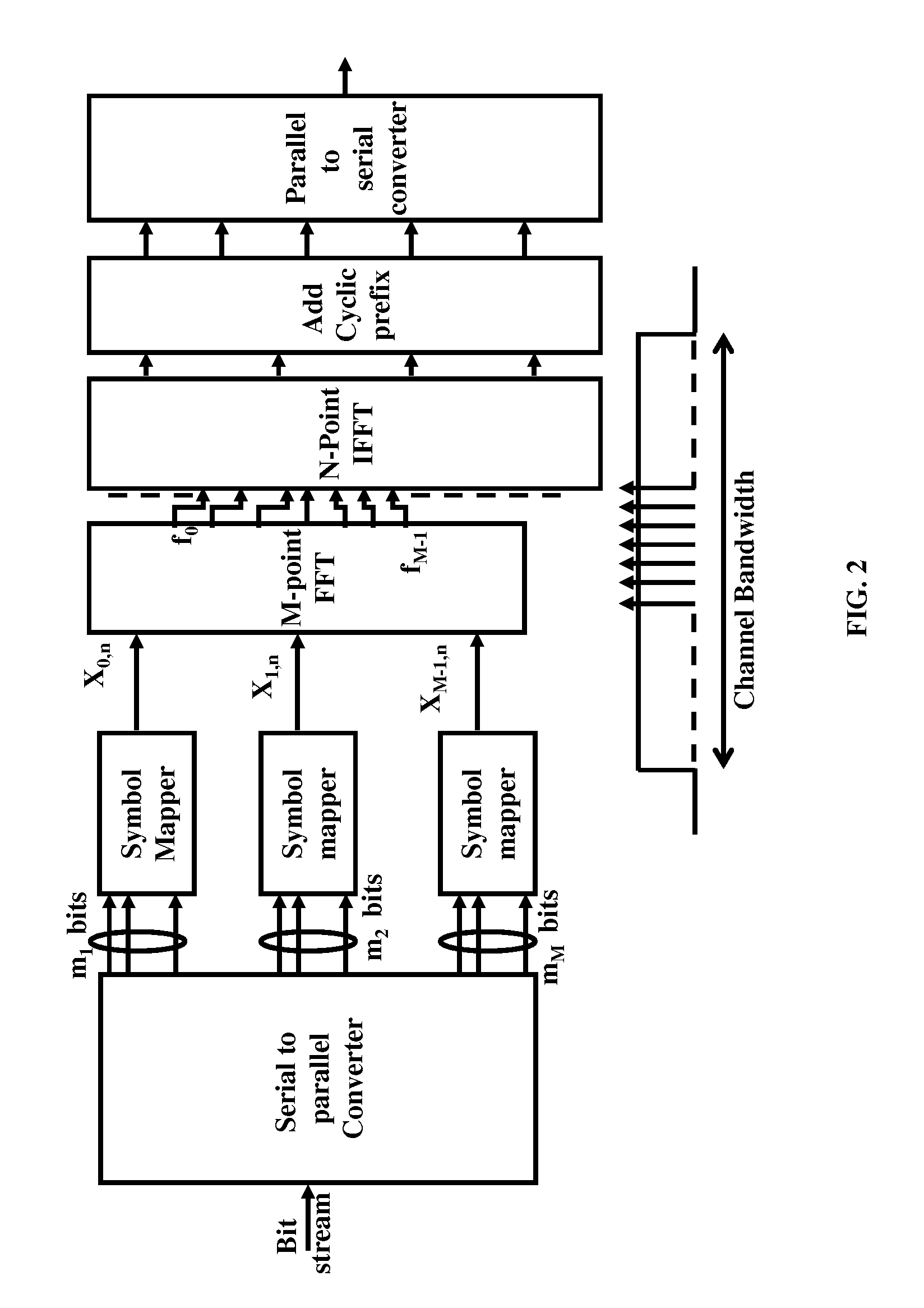
[0049]The embodiments herein achieve transmit diversity and precoding using multiple antennas in wireless networks. Referring now to the drawings, and more particularly to FIGS. 1 through 23, where similar reference characters denote corresponding features consistently throughout the figures, t...


PUM


Abstract

Precoding for multiple transmission streams in multiple antenna systems. Disclosed herein is a general method that transmits signal from multiple antennas using a one / two dimensional precoder. This precoder is fixed in a given resource block (RB) or slot, which is composed of P subcarriers and Q OFDM symbols (where the values for P and Q are greater than or equal to 1). The precoder in each resource block may take same or different values, which span the two dimensional time-frequency grid. The precoder is chosen as a function of either logical frequency index or physical frequency index of the RB.

Description

CROSS-REFERENCE TO RELATED APPLICATIONS[0001]This application is a divisional patent application of U.S. patent application Ser. No. 12 / 999,894 filed on Jan. 21, 2011, which claims priority to PCT application number PCT / IN2009 / 000352, filed on Jun. 18, 2009, which also claims priority to Indian provisional application number 1486 / CHE / 2008, filed on Jun. 18, 2008 and Indian provisional application number 31 / CHE / 2009, filed on Jan. 7, 2009, the contents of which, in their entireties, are herein incorporated by reference.FIELD OF INVENTION[0002]This invention relates to wireless communications, and more particularly to using multiple transmission antennas in wireless communications.BACKGROUND OF INVENTION[0003]A wireless network generally comprises of many smaller region called a cell that is further divided in to multiple sectors. Each cell / sector may have a base station (BS) and multiple mobile stations (MSs). The MSs in a sector may be fixed, nomadic or mobile. Communication from a ...

Claims


Application Information

Patent Timeline
Patent Type & Authority Applications(United States)
IPC IPC(8): H04L27/26H04B7/06H04B7/04H04L27/20
CPCH04L27/2646H04L27/261H04L27/2649H04B7/0456H04L27/20H04B7/0626H04B7/0632H04L27/2628H04L5/0023H04L27/2636H04L27/2647H04L1/0656H04L25/0224H04L27/26526
Inventor KUCHI, KIRAN KUMARJENISTON, DEVIRAJ KLUTTO MILLETHRAMASWAMY, VINODDHIVAGAR, BASKARANGIRIDHAR, KRISHNAMURTHIRAMAMURTHI, BHASKARKALATHIL, DILEEP MANISSERISURYASARMAN, PADMANABHAN MADAMPU
Owner CENT OF EXCELLENCE & WIRELESS TECH
Learn More