Release valve for inflatable seat cushion

a technology for releasing valves and seat cushions, which is applied to fluid mattresses, functional valve types, cycle equipments, etc., can solve the problems of developing discomfort, soreness and even numbness in these regions, and other vehicles, such as bicycles, motor scooters and the like, can suffer from similar discomforts, so as to reduce the risk of accidental air release

Active Publication Date: 2015-10-01
ROHO
View PDF19 Cites 8 Cited by
  • Summary
  • Abstract
  • Description
  • Claims
  • Application Information

AI Technical Summary

Benefits of technology

[0007]In one aspect, a release valve for connection to an inflatable cushion comprising an air conduit, a fitting at a first end of the air conduit for insertion into an air tube, the air tube being in fluid communication with the interior of the cushion, and an air inlet port at the opposite end of the air conduit. There may be a filter assembly at the air inlet port. There is first, vertically orientated, spring biased ball valve in a housing centrally positioned in the air conduit. The housing includes at least one air egress vent. The first ball valve is operatively associated with a spring biased actuator in the ball valve housing for opening the first ball valve. In one aspect, the actuator is a spring biased button. There is a gap or disconnect between the button and the ball valve to minimize the risk of accidental air release. There is a second longitudinally orientated, spring biased ball valve in the air conduit adjacent the air inlet port.
[0008]In use, the cushion is inflated by pumping air through the filtered air inlet port. The pump creates sufficient pressure to overcome the bias strength of the spring to open the second ball valve and allow ingress of air through the air conduit and into the cushion. If the cushion is overinflated, the user depresses the button to overcome the biasing force of the spring, as well as to overcome the biasing force against the first ball valve to allow airflow from the cushion back through the first ball valve and out through vents in the first ball valve housing.

Problems solved by technology

If the rider is seated for long periods of time he can develop discomfort, soreness and even numbness in these regions of the anatomy due to pressure and vibration on the nerves.
Furthermore, riders of other vehicles, such as bicycles, motor scooters and the like can suffer from similar discomforts.

Method used


Image

  • Release valve for inflatable seat cushion
  • Release valve for inflatable seat cushion
  • Release valve for inflatable seat cushion

Examples


Embodiment Construction

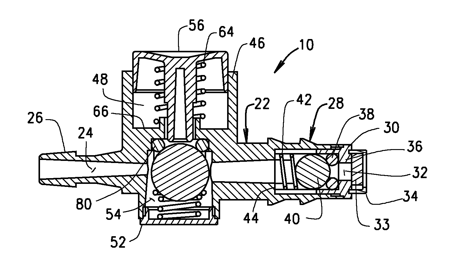
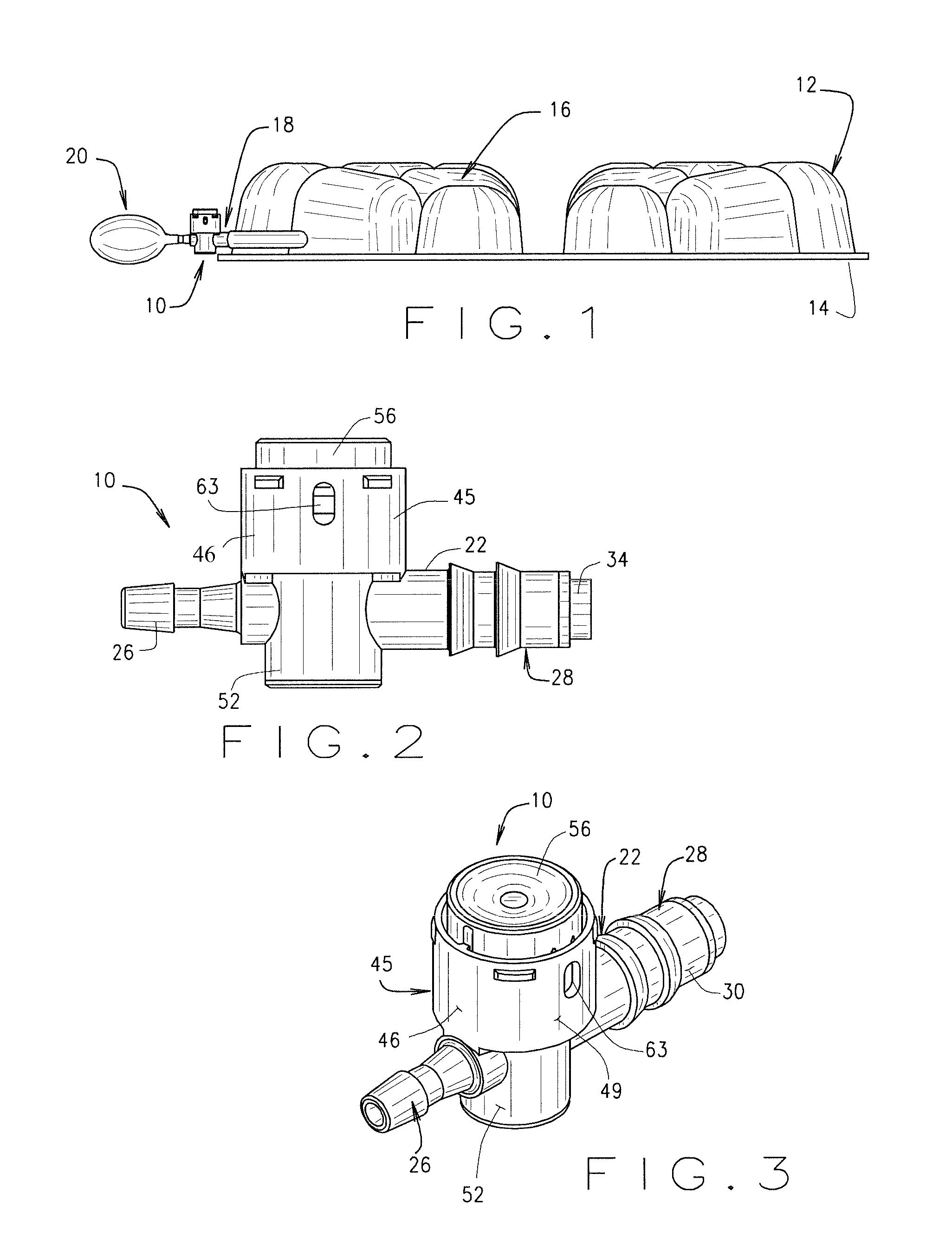
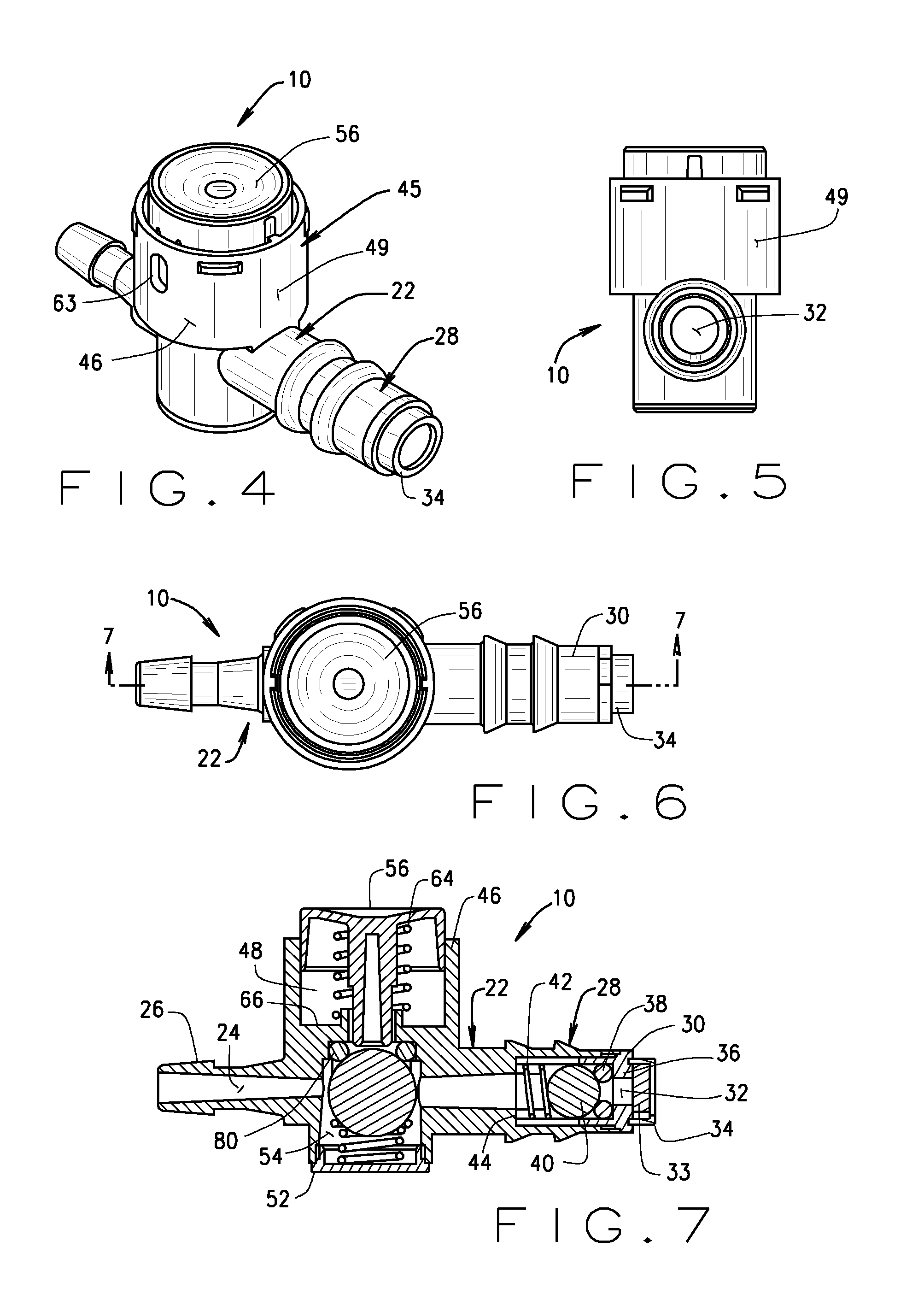
[0020]One aspect of a release valve for an inflatable cushion is indicated generally be reference number 10 in the drawings. FIG. 1 shows release valve 10 functionally attached to an inflatable motorcycle seat cushion, indicated generally by reference number 12 in the drawings. Although referred to as a motorcycle cushion for brevity and clarity, it will be appreciated the cushion can be employed with any seat, particularly, but not limited to, seats on vehicles, either self-propelled or motorized. The cushion can be an inflatable air cell cushion for medical or therapeutic use as well. Cushion 12 includes a base 14 with a plurality of upstanding air inflation cells 16 arranged in an array on the base. In one aspect, cells 16 are inflatable air cells and are generally hollow open-bottomed cells connected by a web which comprises the top layer of base 14. In one aspect, the web and cell arrangement are dip molded from neoprene, as disclosed in U.S. Pat. No. 4,541,136, which is incorp...


PUM


Abstract

A release valve for connection to an inflatable cushion comprising an air conduit, a fitting at a first end of the air conduit for insertion into an air tube in fluid communication with the interior of the cushion, and an air inlet port at the opposite end of the air conduit and a filter assembly at the air inlet port. There is first, vertically orientated, spring biased ball valve centrally positioned in the air conduit including at least one air egress vent and being operatively associated with a spring biased actuator in the ball valve housing for opening the first ball valve. The button and first ball valve define a gap to minimize accidental air release. A second longitudinally orientated, spring biased ball valve is positioned in the air conduit adjacent the air inlet port.

Description

CROSS REFERENCE TO RELATED APPLICATIONS[0001]This application claims the benefit of U.S. Provisional Application Ser. No. 61 / 969,993 filed Mar. 25, 2014 which is incorporated herein by reference.STATEMENT REGARDING FEDERALLY SPONSORED RESEARCH OR DEVELOPMENT[0002]Not Applicable.BACKGROUND OF THE INVENTION[0003]The application relates generally to valves for inflatable apparatus, more specifically, to a release valve for an inflatable seat cushion to bleed air from an inflated cushion to equalize pressure on various points of a seated user's anatomy.[0004]Inflatable seat cushions are well known. They are employed in all types of seating applications including vehicle seating. One particularly useful application of inflatable cushions, such as inflatable air cell cushions, is in motorcycle seating. In general, a motorcycle seat is constructed to support the seated rider's buttocks and, depending upon the size and style, a portion of the upper thigh. Most motorcycle seats or saddles ar...

Claims


Application Information

Patent Timeline
Patent Type & Authority Applications(United States)
IPC IPC(8): A47C27/08B62J1/26
CPCB62J1/26A47C27/081Y10T137/3584Y10T137/87845
Inventor HOPP, DAVID MICHAELSPROUSE, II, ANTHONY ERIC
Owner ROHO
Why Eureka
Try Eureka