
Vehicle antenna with light-emitting body

a technology of vehicle antenna and light-emitting body, which is applied in the direction of antenna equipment with additional functions, antenna adaptation in movable bodies, transportation and packaging, etc., can solve the problems of significant reduction of communication sensitivity, inability to provide original characteristics of the antenna element 103, and inability to meet communication, etc., to achieve satisfactory communication sensitivity and improve visibility.

Inactive Publication Date: 2015-10-01
HONDA LOCK MFG CO LTD
View PDF3 Cites 18 Cited by
  • Summary
  • Abstract
  • Description
  • Claims
  • Application Information

AI Technical Summary

Benefits of technology

This invention helps prevent communication problems by eliminating blind spots and provides better sensitivity in all directions. Additionally, the entire casing emits light, improving visibility while maintaining the antenna's characteristics.

Problems solved by technology

As a result, there is a possibility that the antenna element 103 cannot provide the original characteristic.
As a result, there is a problem where a mill point N (the point where the communication sensitivity is significantly reduced) occurs at the rear of the antenna element 103 or similar problem.
Thus, the communication might not be satisfied.

Method used


Image

  • Vehicle antenna with light-emitting body
  • Vehicle antenna with light-emitting body
  • Vehicle antenna with light-emitting body

Examples


Embodiment Construction

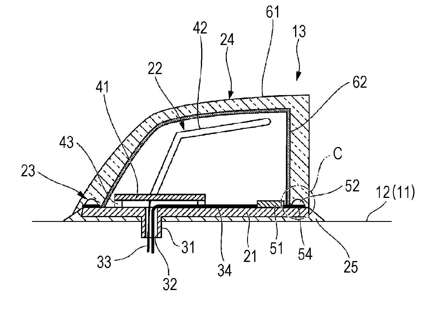
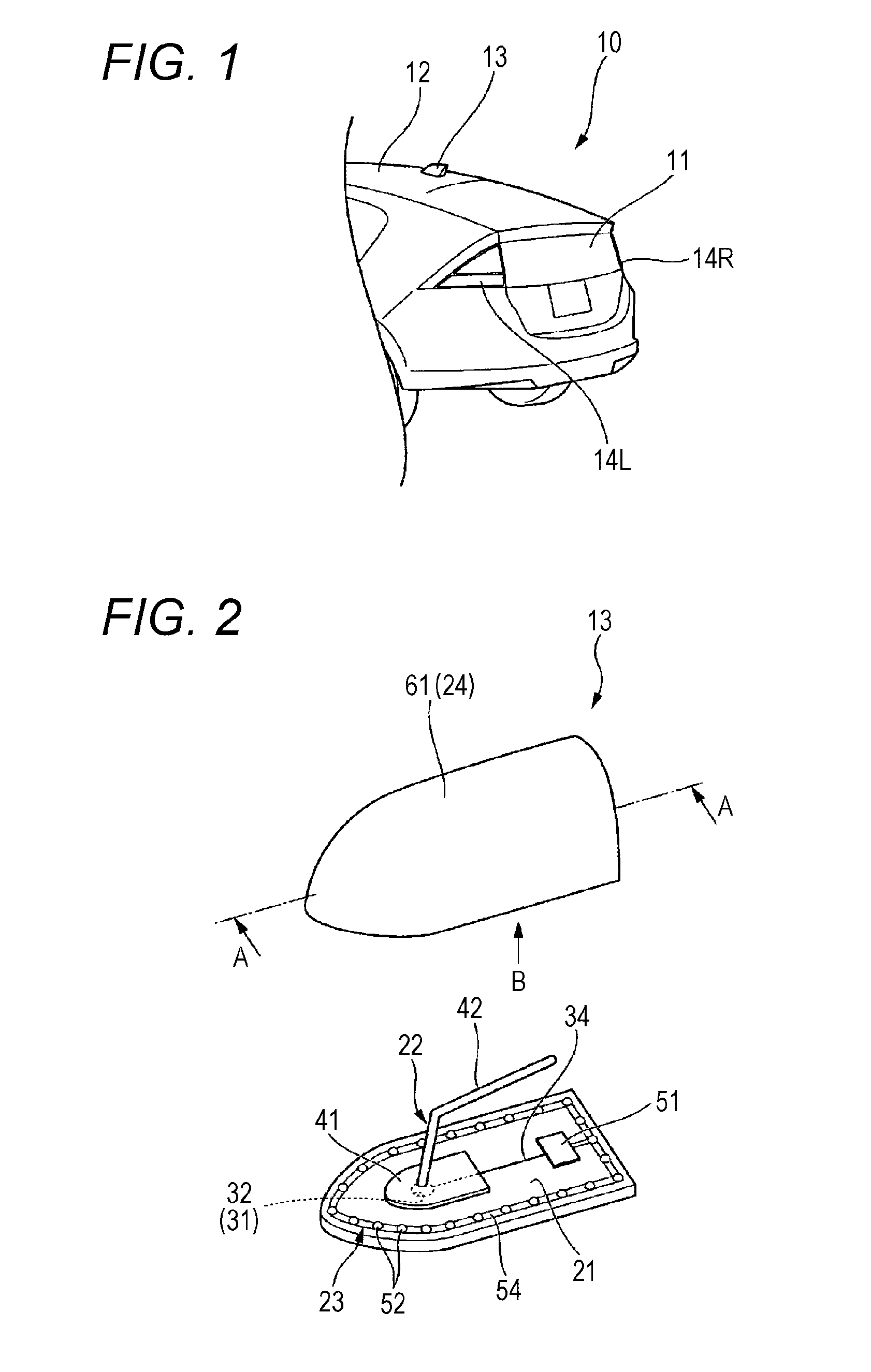
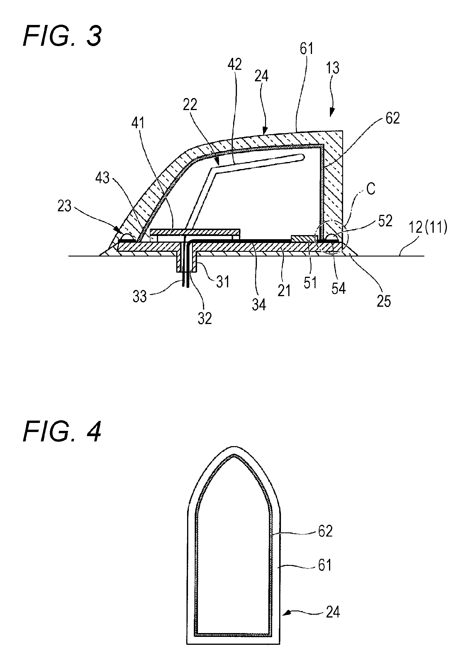
[0024]The following describes the embodiments of the present invention based on the drawings. In this embodiment, the case where a vehicle antenna 13 (hereinafter referred to simply ply as the antenna device 13) with alight-emitting body of the present invention is mounted on a four-wheeled vehicle 10 will be described as an example.

(Vehicle)

[0025]FIG. 1 is a partial perspective view of a vehicle viewed obliquely from the rear side. Here, the directions such as front-to-back and side-to-side directions in the following description are the same as those directions in the vehicle unless otherwise stated. As illustrated in FIG. 1, on the vehicle 10 (hereinafter referred to also as the own vehicle 10) in this embodiment, the antenna device 13 is installed in the rear end portion of a roof panel 12 of a vehicle body 11 and in the center of the right-left direction.

[0026]Here, on both right and left sides in the front portion and the rear portion of the vehicle body 11, turn-signal lights...


PUM


Abstract

Provided is a vehicle antenna with a light-emitting body that allows improving visibility while maintaining the characteristic of an antenna element.The vehicle antenna with a light-emitting body includes: a base 21; an antenna element 42 arranged on the base 21; a light-emitting body 52 that is arranged on a peripheral edge portion of the base 21 and positioned below the antenna element 42; and a casing 24 that covers the antenna element 42 from an upper side so as to house the antenna element 42. The casing 24 is formed of a light transmissive material, and a lower-end opening edge of the casing 24 is arranged at an upper side of the peripheral edge portion of the base 21.

Description

TECHNICAL FIELD[0001]The present invention relates to a vehicle antenna with a light-emitting body.BACKGROUND ART[0002]Conventionally, an antenna device is mounted on the roof panel of a vehicle body to receive the signals of television, radio, and similar service. Mounting an antenna device for receiving GPS, an antenna device for receiving the signal transmitted from a FOB key, and similar device on the roof panel in the future is under consideration. As this antenna device, what is called a shark fin antenna, which has a fin-shaped casing, disposed on the roof panel to protrude upward, is known. Inside this fin-shaped casing, an antenna element is housed.[0003]Here, for example, Patent Literature 1 discloses the following configuration. In this configuration, a light-emitting, body such as an LED is mounted on the outer surface of the casing. This light-emitting body lights in conjunction with: lighting of a turn-signal light as an answer back to a turn signal operation and a FOB...

Claims


Application Information

Patent Timeline
Patent Type & Authority Applications(United States)
IPC IPC(8): H01Q1/32B60Q1/44B60Q1/26
CPCH01Q1/3275B60Q1/44B60Q1/2611H01Q1/06H01Q1/22H01Q1/42B60Q1/2661B60Q1/482H01Q1/44
Inventor ISO, HIROKI
Owner HONDA LOCK MFG CO LTD
Learn More