System with dual function load board

a load board and dual function technology, applied in automated test systems, instruments, measurement devices, etc., can solve the problems of delay in product release time to market, cost and labor of hardware and software used in these two tests,

Inactive Publication Date: 2015-10-08
KAO CHARLES TZU TAI
View PDF8 Cites 5 Cited by
  • Summary
  • Abstract
  • Description
  • Claims
  • Application Information

AI Technical Summary

Benefits of technology

[0007]Another objective of the present invention is to provide a system with dual function load board, so both of the Bench test and the ATE test can be operated in the system with dual function load board so as to minimize the inaccuracy of the test correlation between the Bench test and the ATE test.

Problems solved by technology

The hardware and software used in these two tests run up costs and labor.
Also, these tests would delay product release time to market.

Method used


Image

  • System with dual function load board
  • System with dual function load board
  • System with dual function load board

Examples


Embodiment Construction

[0020]The above-mentioned description of the present invention can be best understood by referring to the following detailed description of the preferred embodiments and the accompanying drawings.

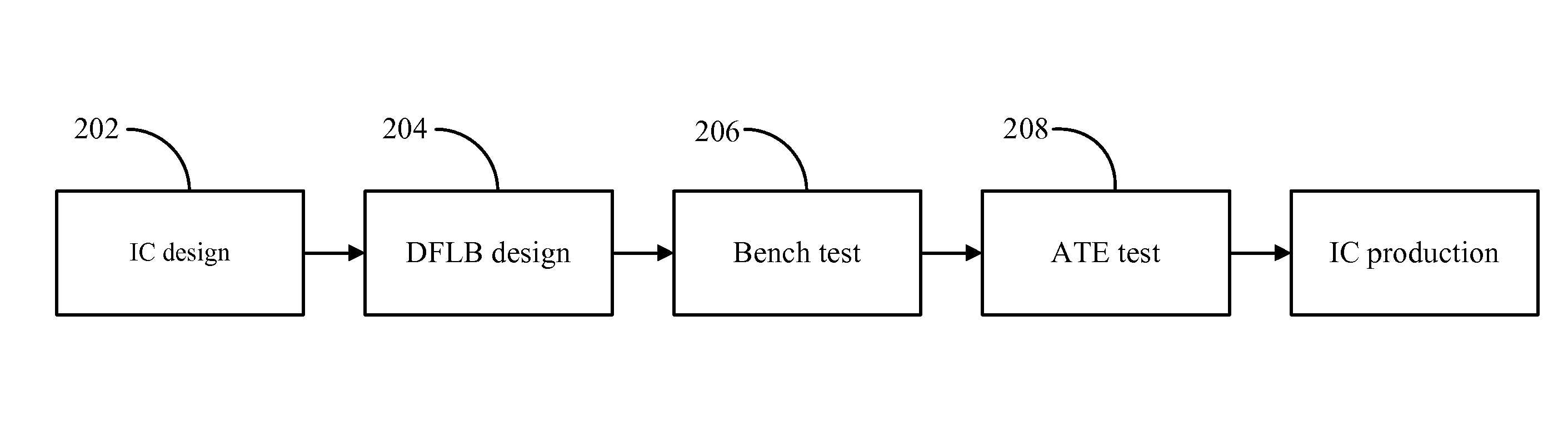
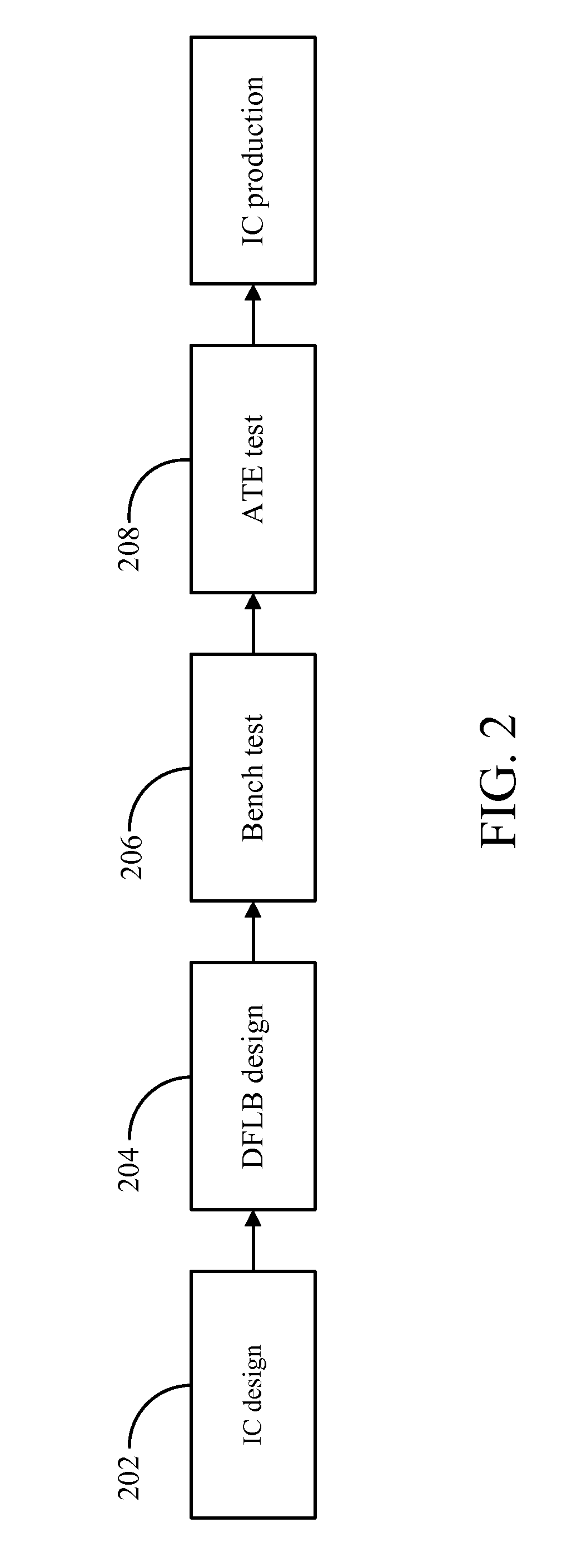
[0021]FIG. 2 is a test flow illustrating a system with dual function Load Board (DFLB) in this invention. As shown in FIG. 2, in a stage 202, an IC design is processed. The IC design in this stage is performed by Engineers and the ICs can be any different kinds of ICs, such as digital ICs or analog ICs, and it is not limited herein. After the IC design is performed, a dual function load board is developed in stage 204 to test the ICs and the dual function load board in the present invention can be used in both the Bench test in stage 206 and the ATE test in stage 208. Since the conventional load board is larger than the conventional bread board, the dual function load board in the present invention is a modified load board which includes the functions in both of the conventional load board ...


PUM


Abstract

A system with dual function load board is provided herein, and the system with dual function load board comprises a programmable module, a dual function load board and a software application with user interface. The programmable module is configured for emulating an Automatic Test Equipment (ATE) when performing ATE test. The dual function load board is electrically connected to the FPGA module and configured for performing the ATE test and a Bench test. The software application with user interface (UI) is configured for providing an interface to perform tests.

Description

FIELD OF THE DISCLOSURE[0001]The present invention relates to the field of a system with dual function load board, and more particularly relates to a system with dual function load board to perform both of Bench test and Automatic Test Equipment (ATE) test.BACKGROUND OF THE INVENTION[0002]The test of Integrated Circuit (IC) chips can be divided into Bench test and ATE test. A Bench test is processed by Research and Development (R&D) engineers. A Bench test is the process of characterizing the failure mode of the IC sample using various pieces of bench equipment for exciting the device and measuring its responses. The equipment required for effective failure verification includes various power supplies, multi-meters, frequency counters, oscilloscopes, curve tracers, break-out boxes, and the like. Sometimes it is also necessary to build a circuit that simulates the application of the customer where the failure was observed. The idea is to be able to observe the failure of the sample i...

Claims


Application Information

Patent Timeline
Patent Type & Authority Applications(United States)
IPC IPC(8): G01R31/28
CPCG01R31/2834G01R31/2844G01R31/2851G01R31/2889
Inventor KAO, CHARLES TZU-TAI
Owner KAO CHARLES TZU TAI
Why Eureka
Try Eureka