Plate for camera equipment

a technology for camera equipment and brackets, applied in the field of brackets, can solve the problems of difficult use of viewfinders, difficult to change the orientation of camera equipment attached to a ballhead from landscape to portrait, and limited rotation in directions transverse to the axis of the stem

Active Publication Date: 2015-10-08
REALLY RIGHT STUFF
View PDF12 Cites 17 Cited by
  • Summary
  • Abstract
  • Description
  • Claims
  • Application Information

AI Technical Summary

Problems solved by technology

While the ball can be rotated 360° around the longitudinal axis of the stem, rotation in directions transverse to the axis of the stem is limited by interference between the stem and the edge of the ballhead's body.
Changing the orientation of camera equipment attached to a ballhead from landscape to portrait or vice versa can be problematic.
If the camera equipment is heavy, the horizontal movement of the weight may destabilize the support and the vertical displacement of the camera may make using the viewfinder difficult.
In addition, if the support is not sitting on a level surface, it may not be possible to rotate the ball far enough to attain the portrait orientation before the stem of the ball makes contact with the bottom of the drop notch.
While an L-plate facilitates photography with a tripod, monopod or other support, use of an L-plate with a digital camera can be problematic.
A cable relief spacer may be inserted between the L-plate and the receiver to provide clearance for connectors and cables but this is, typically, a small, loose piece which can be easily misplaced and may not be carried with the camera equipment and, therefore, may be unavailable when needed.
Also, the interconnection of the L-plate to the camera tends to be awkward, and the adjustment of the L-plate tends to be limited and complicated, and the L-plate tends to increase the instability to supporting the camera.

Method used


Image

  • Plate for camera equipment
  • Plate for camera equipment
  • Plate for camera equipment

Examples


Embodiment Construction

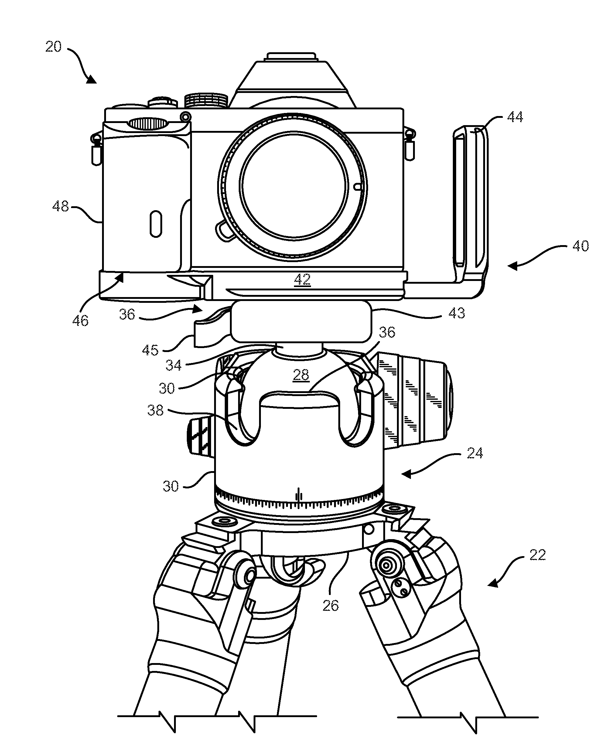
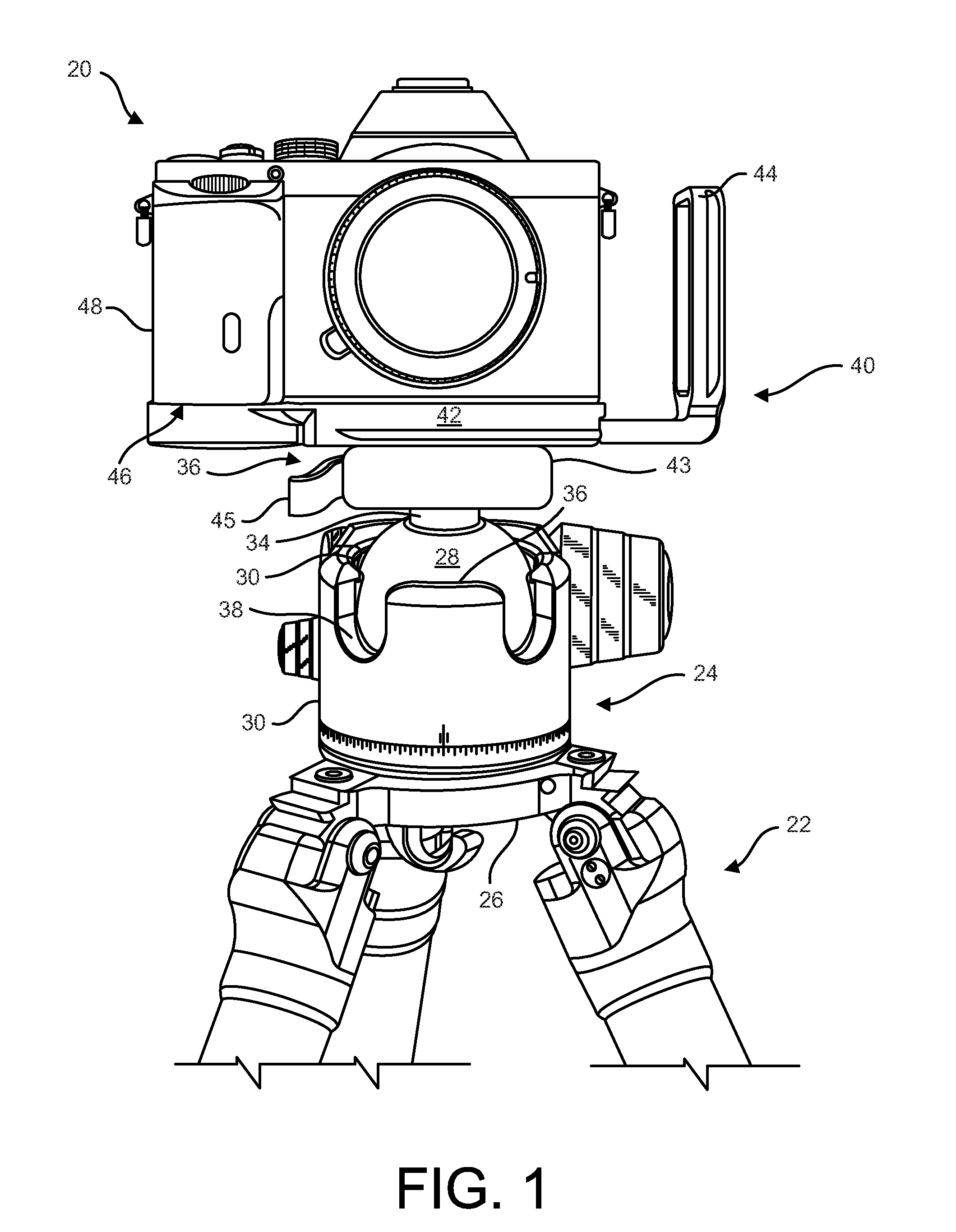
[0027]Referring in detail to the drawings where similar parts are identified by like reference numerals, and, more particularly to FIG. 1, to provide stability and to reduce blurring, photographic equipment 20, for example, a camera body 48, a lens and one or more accessories, is often affixed to a support, such as a tripod 22 or monopod. While camera equipment 20 can be attached directly to a tripod 22 or other support, cameras are commonly affixed to a support with an intermediate device, such as a ballhead 24, pan head or gimbal head which is usually secured to the head mount 26 of the support by a screw that projects upward through the head mount into threaded engagement with a threaded aperture in the body of the intermediate device. A ballhead 24 comprises generally a ball 28 which is retained in a socket 30 in the ballhead's body 32. The ball 28 typically includes a radially projecting stem 34 to which the photographic equipment or a receiver of a quick-release system is atta...


PUM


Abstract

A plate provides clearance between a camera and a quick-release receiver securing the camera to a support.

Description

CROSS-REFERENCE TO RELATED APPLICATIONS[0001]This application claims the benefit of U.S. Provisional App. No. 61 / 953,467, filed Mar. 14, 2014.BACKGROUND OF THE INVENTION[0002]The present invention relates to a bracket suitable for interconnecting camera equipment and a support for camera equipment and, more particularly, to an L-plate bracket facilitating changing the orientation of a supported camera equipment between landscape and portrait orientations.[0003]Camera equipment often includes a threaded receptacle for attaching the equipment to a head mount of a tripod, monopod or other support. A camera may be attached directly to a head mount of a support by a screw projecting from the head mount but a quick-release mounting system is commonly used to secure camera equipment, particularly higher end camera equipment, to a tripod or other support. A quick-release camera mounting system typically includes a plate that is securable to the camera' body by a screw that is engageable wit...

Claims


Application Information

Patent Timeline
Patent Type & Authority Applications(United States)
IPC IPC(8): G03B17/56H04N5/225H04N5/232
CPCG03B17/561H04N5/2253H04N5/23245F16M11/041F16M11/2014F16M2200/022F16M11/28F16M11/14F16M11/242H04N23/50F16M11/24G03B17/56H04N23/54H04N23/667F16M11/08
Inventor JOHNSON, SR., JOSEPH M.BURK, MATTHEW L.
Owner REALLY RIGHT STUFF
Why Eureka
Try Eureka