

Method and System of Video Wall Setup and Adjustment Using GUI and Display Images
a technology of video wall and image, applied in the field of network addressable display, can solve the problems of laborious tasks, critical setup of output display, and laborious fine tuning
- Summary
- Abstract
- Description
- Claims
- Application Information
AI Technical Summary
Benefits of technology
Problems solved by technology
Method used
Image

Examples
Embodiment Construction
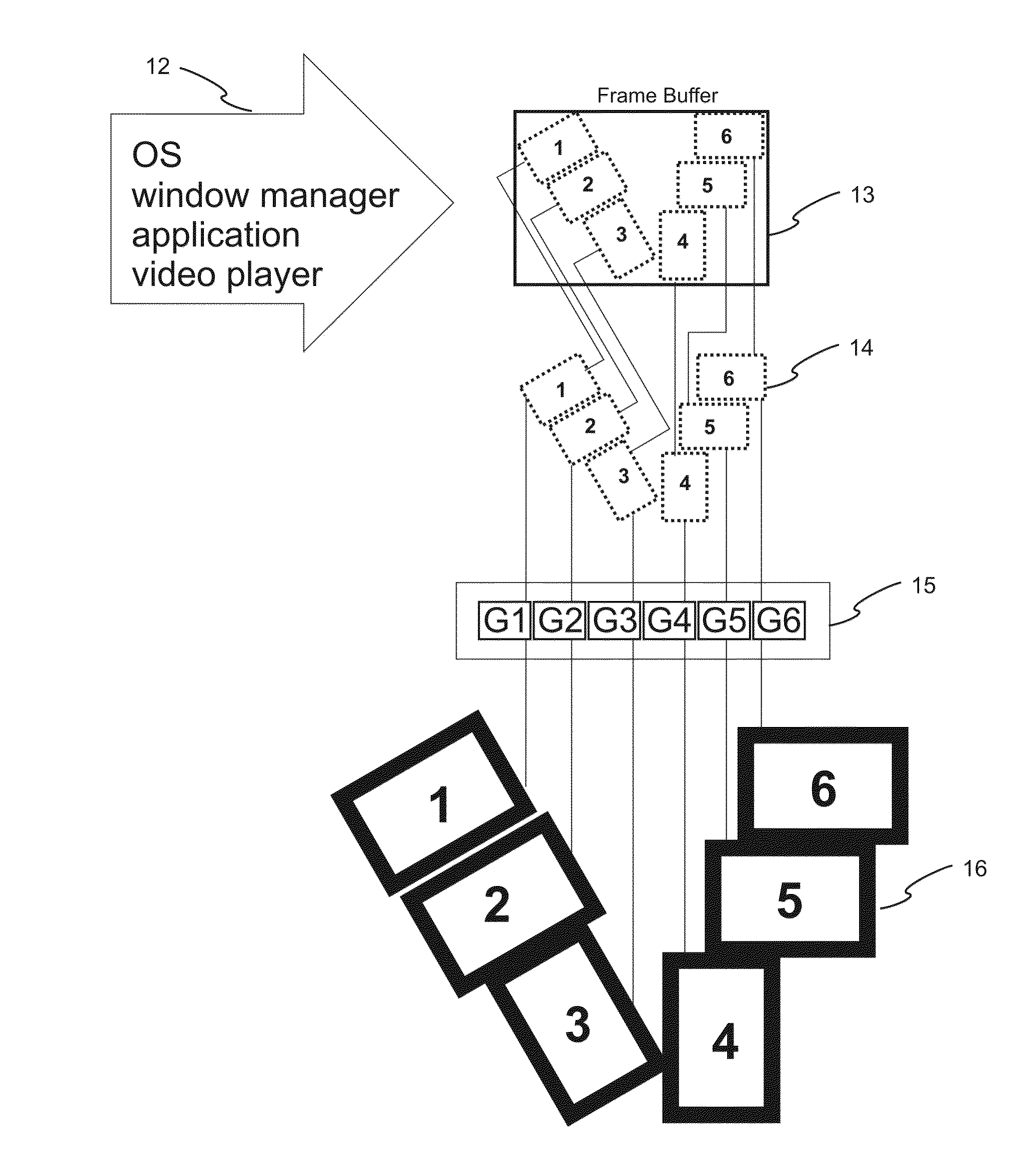
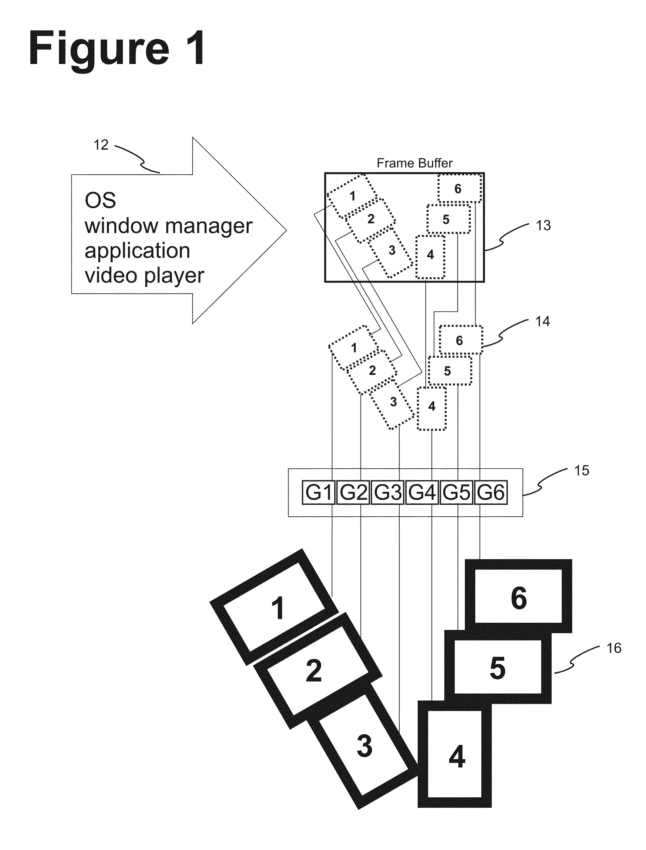
[0007]A video wall server splits source-video into sub-images and distributes these sub-images to multiple listening display devices. Built-in algorithms optimize, parse and scale the individual video-wall segments. To accomplish this splitting efficiently it is beneficial to create a configuration file stored in a computer readable medium using information on the position, configuration and settings for each of individual physical display and how they relate to the video-wall canvas. Using such a configuration file allows the video wall server to efficiently create a seamless canvas across the display units. This invention deals with methods of supplying the information for the creation of such files by means of user feedback base on test-canvasses and to sequentially changing the configuration file before redeploying a test-canvas to further improve the overall viewer-image.
[0008]Configuration of Displays: This invention provides methods equipping the server with a configuration f...
PUM
 Abstract
Description
Claims
Application Information