connector

Active Publication Date: 2015-10-08
YAZAKI CORP
View PDF12 Cites 5 Cited by
  • Summary
  • Abstract
  • Description
  • Claims
  • Application Information

AI Technical Summary

Benefits of technology

[0007]In consideration of the above-mentioned circumstances, the object of the present invention is t

Problems solved by technology

In the case of the above-mentioned connector in which the male terminals protrude from the tip end of the housing, a mating connector, foreign matter, etc. may interfere with the portions of the male terminals protruding from the housing, and the male terminals may be deformed or damaged.
Hence, when the connector is conn

Method used


Image

  • connector
  • connector
  • connector

Examples


Embodiment Construction

[0039]An example of an embodiment according to the present invention will be described below referring to the drawings.

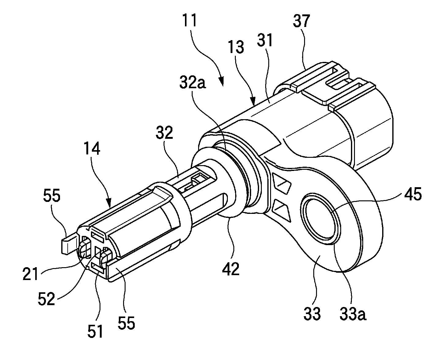
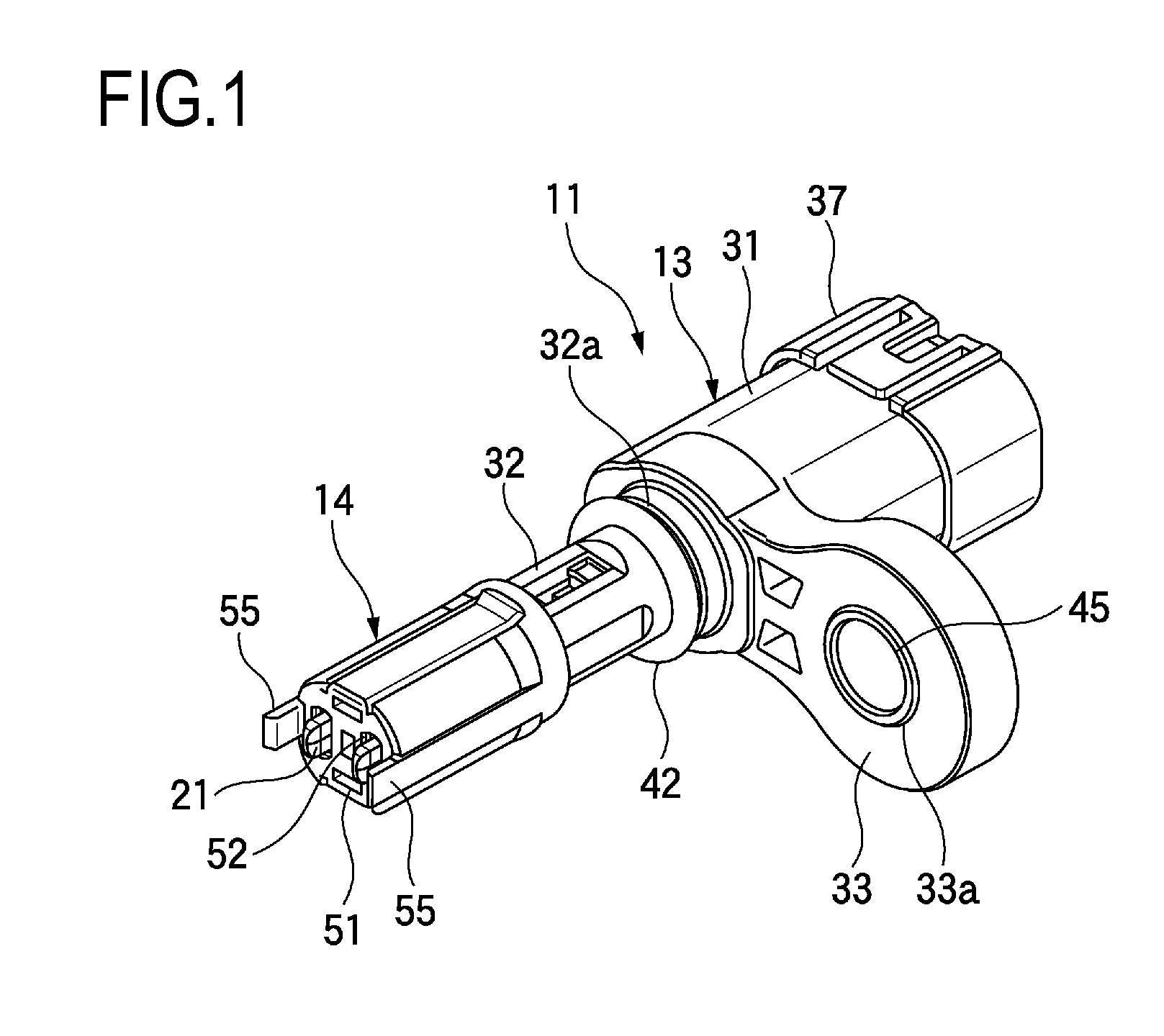
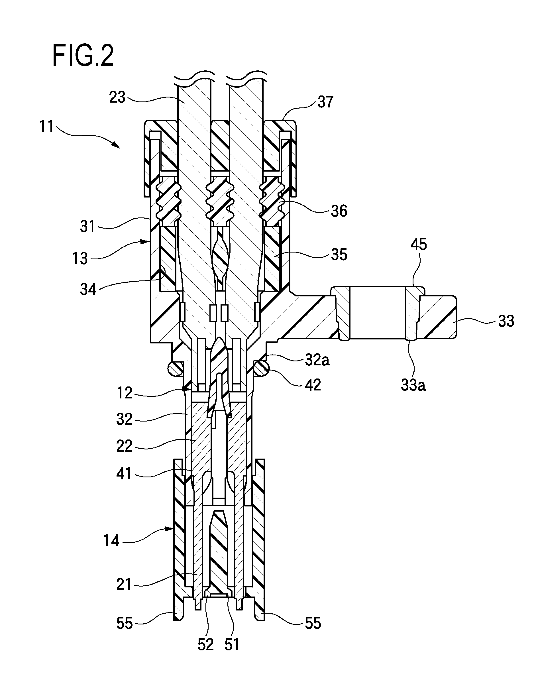
[0040]FIG. 1 is a perspective view showing a connector according to this embodiment. FIG. 2 is a cross-sectional view showing the connector according to this embodiment. FIG. 3 is an exploded perspective view showing the connector according to this embodiment.

[0041]As shown in FIGS. 1 to 3, a connector 11 according to this embodiment is equipped with a pair of male terminals (connection terminals) 12, a housing 13, and a front holder 14.

[0042]The male terminal 12 is made of a conductive metal material, its tip end side is a tab terminal section (sometimes referred to as a terminal section) 21 that is made contact with a mating terminal and conducted and connected thereto, and its rear end side is a crimping section 22 that is connected to the end section of an electric wire 23. The tab terminal section 21 is formed into a rod shape and is inserted into the female te...


PUM


Abstract

A connector includes a connection terminal including a terminal section which is configured to contact with a mating terminal, a housing that holds the connection terminal in a state that the terminal section protrudes from the housing, and a front holder provided on the housing so as to be slidable along an extension direction of the connection terminal. The front holder is disposed at a first position in which the front holder covers a side portion of the terminal section in a case that the front holder slides forward in the extension direction, and the front holder is disposed at a second position in which the side portion of the terminal section is exposed in a case that the front holder slides rearward in the extension direction.

Description

CROSS REFERENCE TO RELATED APPLICATIONS[0001]This application is based on Japanese Patent Application (No. P2014-079450) filed on Apr. 8, 2014, the contents of which are incorporated herein by reference.BACKGROUND OF THE INVENTION[0002]1. Field of the Invention[0003]The present invention relates to a connector equipped with terminals.[0004]2. Description of the Related Art[0005]As a connector to be mounted on an automobile wire harness or the like, a connector is available in which a plurality of male terminals are held in a housing and the tip ends of these male terminals protrude from the tip end of the housing (refer to JP-A-2012-109035).[0006]In the case of the above-mentioned connector in which the male terminals protrude from the tip end of the housing, a mating connector, foreign matter, etc. may interfere with the portions of the male terminals protruding from the housing, and the male terminals may be deformed or damaged. Hence, when the connector is connected to the mating...

Claims


Application Information

Patent Timeline
IPC IPC(8): H01R13/631H01R13/502
CPCH01R13/502H01R13/631H01R13/4538H01R9/03H01R13/5208H01R13/748
Inventor MATSUNAGA, TAKASHI
Owner YAZAKI CORP
Why Eureka
Try Eureka