Hydraulically actuated tool and valve assembly therefor
- Summary
- Abstract
- Description
- Claims
- Application Information
AI Technical Summary
Benefits of technology
Problems solved by technology
Method used
Image
Examples
Embodiment Construction
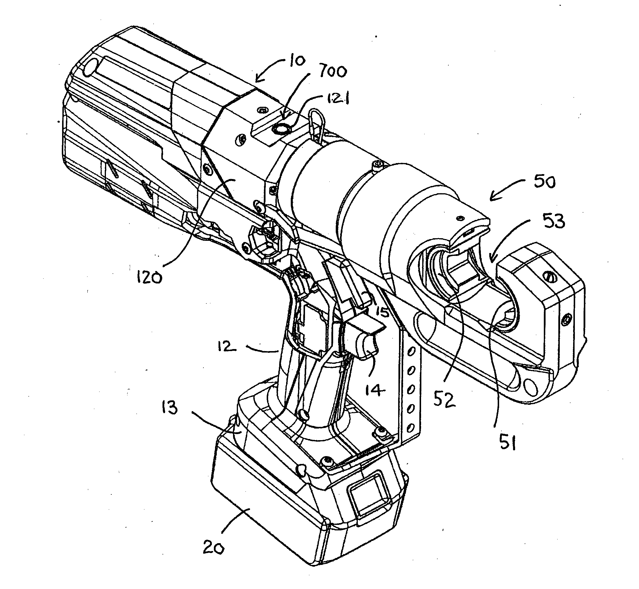
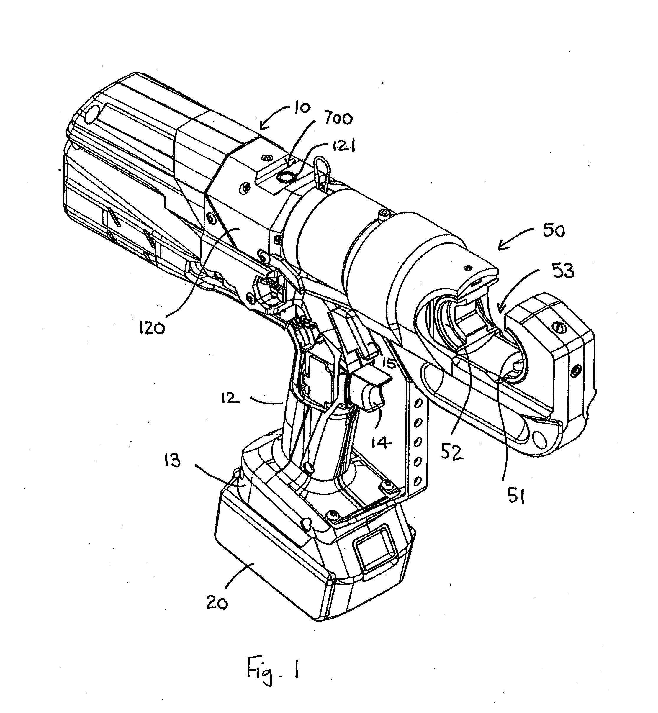
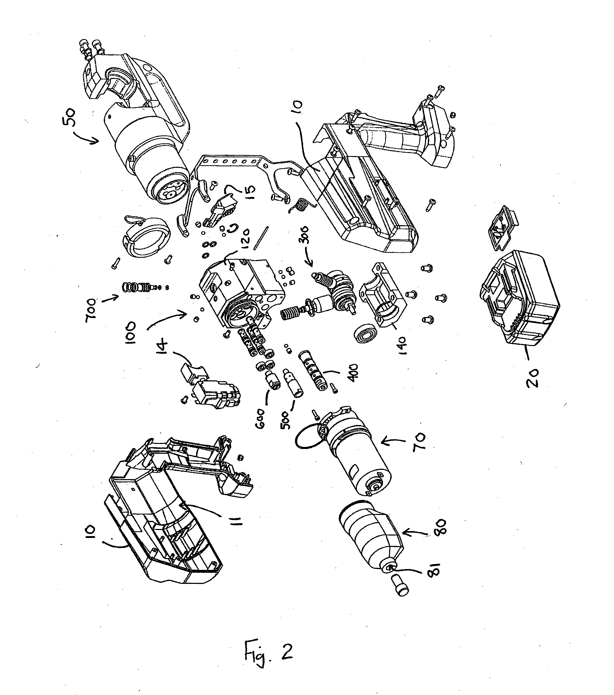
[0083]FIGS. 1 and 2 of the accompanying drawings depict an hydraulically actuated tool, in the form of an hydraulic crimping tool. The crimping tool has a two-part casing 10 defining a housing 11 for receipt of various functional components of the tool, as will be described in detail below, and an operator handle 12 depending from the housing 11. The base 13 of the handle 12 is configured to receive a battery pack 20 to electrically power the tool. An operating trigger 14 is mounted on the front of the handle 12. The tool has a head assembly 50 having first and second opposing jaws 51, 52 with a recess 53 defined therebetween for receipt of a connector or splice to be crimped. The first jaw 51 is fixed whilst the second jaw 52 is an actuable member that, in operation, is displaced towards the first jaw 51 under pressure to crimp the connector or splice between the first and second jaws 51, 52.
[0084]Referring specifically to FIG. 2, within the housing 11 is mounted a body assembly 10...
PUM
| Property | Measurement | Unit |
|---|---|---|
| Pressure | aaaaa | aaaaa |
| Flow rate | aaaaa | aaaaa |
| Area | aaaaa | aaaaa |
Abstract
Description
Claims
Application Information
 - R&D Engineer
- R&D Manager
- IP Professional
- Industry Leading Data Capabilities
- Powerful AI technology
- Patent DNA Extraction
Browse by: Latest US Patents, China's latest patents, Technical Efficacy Thesaurus, Application Domain, Technology Topic, Popular Technical Reports.
© 2024 PatSnap. All rights reserved.Legal|Privacy policy|Modern Slavery Act Transparency Statement|Sitemap|About US| Contact US: help@patsnap.com


