Electronic device with cooling by a liquid metal spreader

Active Publication Date: 2015-10-08
INSTITUT NAT POLYTECHN DE GRENOBLE +2
View PDF4 Cites 16 Cited by
  • Summary
  • Abstract
  • Description
  • Claims
  • Application Information

AI Technical Summary

Problems solved by technology

The thickness of such a spreader is optimal; below this thickness, spreading is insufficient which degrades the performances of the cooling device.
Above this thickness, the temperature resistance added by it becomes too high.
However, copper is heavy and this is why

Method used


Image

  • Electronic device with cooling by a liquid metal spreader
  • Electronic device with cooling by a liquid metal spreader
  • Electronic device with cooling by a liquid metal spreader

Examples


Example

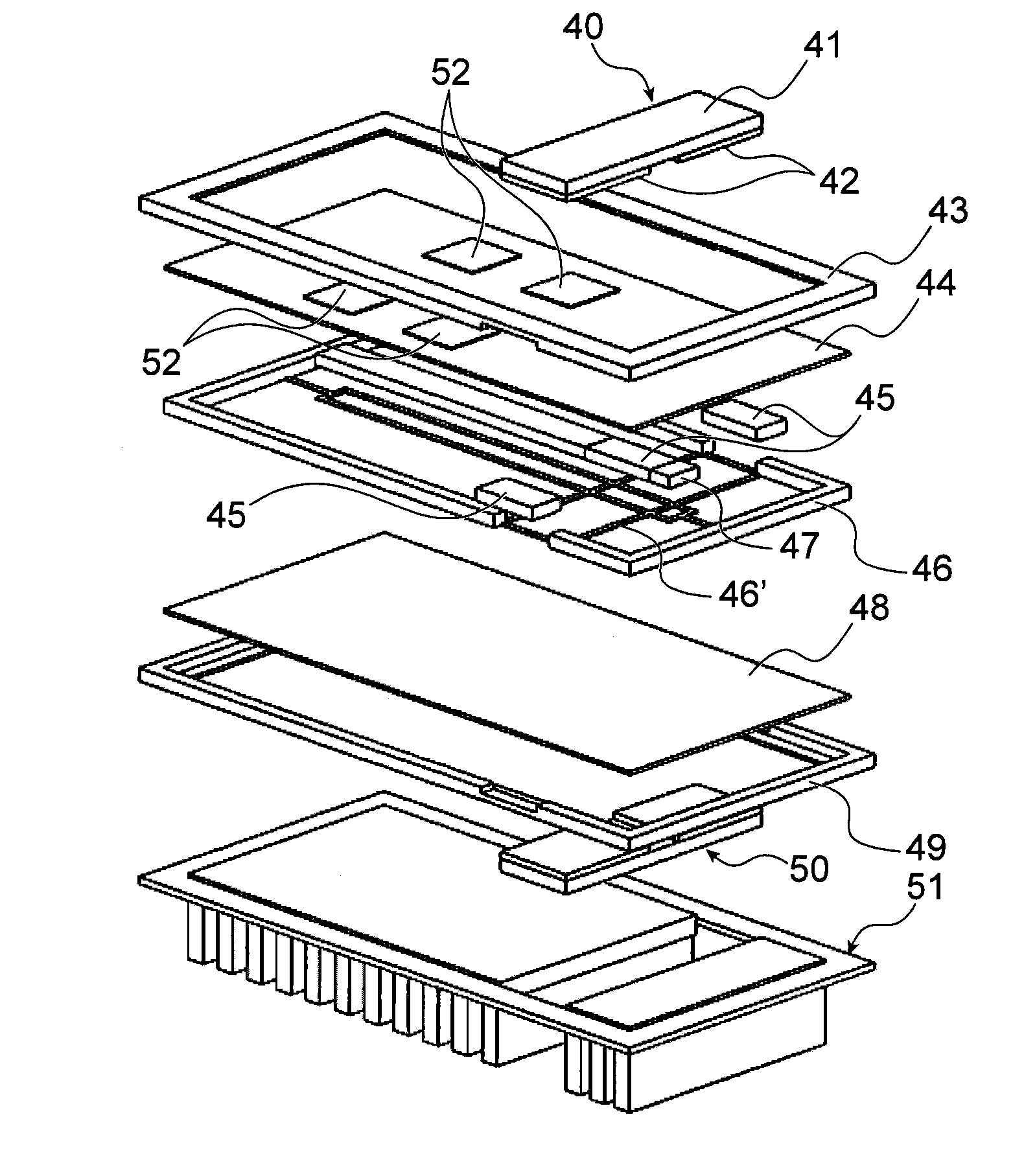
[0077]FIGS. 6A and 6B show a first embodiment of the device according to the invention comprising two electromagnetic pumps each comprising a first and a second electromagnetic circuit generating a magnetic field, and electrodes transporting electrical current.

[0078]FIG. 6A clearly shows the following:[0079]un first magnetic circuit 40 comprising at least one bar made of magnetic material 41 and a permanent magnet 42,[0080]un first polymer frame 43,[0081]a first plate made of an insulating material 44 on which semiconductor components 52 are located,[0082]a bar made of deformable material 47,[0083]three electrodes 45, one of which is arranged on deformable material,[0084]a polymer seal 46 with support means 46′,[0085]a second plate made of insulating material 48,[0086]a second polymer frame 49,[0087]a second magnetic circuit 50,[0088]a heat sink 51,

a liquid metal circulation channel being made around the bar made of deformable material 52.

[0089]In one advantageous embodiment, the de...

Example

[0098]FIGS. 8A and 8B show a second embodiment of the device according to the invention, that corresponds to a power model comprising four electromagnetic pumps.

[0099]FIG. 8A clearly shows the following:[0100]two first magnetic circuits 60 and 61,[0101]a polymer frame 62,[0102]a first ceramic plate 63, on which electronic circuits 64 or several electronic components 65 are placed,[0103]a bar made of deformable material 68,[0104]electrodes 66, 66′, 69, 69′ and electrodes 67 placed on deformable material 68,[0105]a polymer seal 70 with support means 70′,[0106]a second ceramic plate 71,[0107]two second magnetic circuits 72 and 73,[0108]a finned heat sink 74,

a liquid metal circulation channel being made around the bar made of deformable material 68.

Example

[0109]FIGS. 9A and 9B show a third embodiment of the device according to the invention, that corresponds to a model with two superposed liquid metal circulation channels.

[0110]FIG. 9A clearly shows the following:[0111]a first finned heat sink 80,[0112]a first polymer frame 81,[0113]first magnetic circuits 82,[0114]a first ceramic plate 83 on which semiconductor components 84 are located,[0115]first electrodes 85,[0116]a first polymer seal 86, with support means 87,[0117]a second ceramic plate 88,[0118]a second polymer seal 90 with support means 91,[0119]second electrodes 92,[0120]three second bars made of deformable material 93,[0121]a third ceramic plate 95,[0122]second magnetic circuits 96,[0123]a second polymer frame 97,[0124]a second finned heat sink 98,

a first liquid metal circulation channel being made around first bars made of deformable material 92, and a second liquid metal circulation channel being made around second bars made of deformable material 93.

[0125]In order to de...


PUM


Abstract

An electronic device with cooling of a heat dissipation source, by a liquid metals spreader, the device including at least one heat dissipation source, at least one spreader through which at least one liquid metal circulation channel passes forming a loop routed below a heat dissipation source, at least one heat sink, and at least one electromagnetic pump moving the liquid metal in the at least one channel such that the liquid metal absorbs heat dissipated by a heat dissipation source and transports the absorbed heat to be evacuated by the heat sink. Each spreader includes at least two plates made of an electrical insulating material located on each side of at least one bar made of deformable material.

Description

TECHNICAL FIELD[0001]This invention relates to an electronic device, for example a semiconductor device, cooled by liquid metals spreader.STATE OF PRIOR ART[0002]The field of the invention is temperature management of electronic components, for example semiconductors. As shown in FIG. 1, an electronic component may be placed on a cooling device through a metal plate a few millimetres thick. The purpose of this plate is to spread the emitted heat flux and thus increase the cross-section of this heat flux as experienced by the cooling device. Global thermal management is very much improved since temperature gradients are inversely proportional to the exchange area. The term “spreader” is used to denote such a plate throughout the remainder of this description. FIG. 1 shows a dissipation source 10, for example an electronic component or a packaged set of components, arranged on a spreader 11, that spreads the flux before it reaches the cooling device 12 (the arrows show the direction o...

Claims


Application Information

Patent Timeline
IPC IPC(8): H05K7/20
CPCH05K7/20272H05K7/20263H01L23/473H01L2924/0002H01L2924/00
Inventor SALAT, JACQUESAVENAS, YVANMEURET, REGISTAWK, MANSOUR
Owner INSTITUT NAT POLYTECHN DE GRENOBLE
Why Eureka
Try Eureka