Syringe quick disconnect apparatus and related method

Inactive Publication Date: 2015-10-15
NORGREN KLOEHN
View PDF5 Cites 4 Cited by
  • Summary
  • Abstract
  • Description
  • Claims
  • Application Information

AI Technical Summary

Benefits of technology

The patent describes a fluid metering system that can be attached to a syringe dock. The system includes a plunger assembly with a plunger that can be used to aspirate and dispense fluid. The system also includes a driving portion that can actuate the plunger assembly. The system can be used with a polymer syringe dock and has a seal to ensure fluid is in sealed communication with the system. The technical effect of this system is that it provides a convenient and efficient way to measure and control the dispensing of fluids in a laboratory setting.

Problems solved by technology

Positioning the separate sealing member while simultaneously attaching the syringe to the manifold assembly is generally difficult.
One source of difficulty stems from the syringe being typically inserted into a bottom surface of the manifold or some other syringe accepting port.
This makes for a difficult task especially if the syringe being coupled is positioned between two other adjacent syringes, resulting in limited space for a user to maneuver.
This typically takes two hands to accomplish, and also requires a reasonable amount of space between syringes on a manifold for finger clearance during threading.
Overall, the assembly process—inserting and removing syringes to and from manifolds / pumps—becomes increasingly difficult with multi-channel units.
Often, it is necessary that a syringe be replaced or taken off the pump, but because of the pump's compact design, it is very difficult to remove a syringe that is in the middle of neighboring syringes, as there is insufficient space for a person's fingers to provide clearance so to maintain a proper grip.
It is also difficult or at least ill-advised to use a pair of pliers to aid in syringe installation and removal.
Besides risking breakage of a syringe, either not enough torque may be applied onto the syringe assembly or too much torque may be applied.

Method used


Image

  • Syringe quick disconnect apparatus and related method
  • Syringe quick disconnect apparatus and related method
  • Syringe quick disconnect apparatus and related method

Examples


Embodiment Construction

[0088]FIGS. 1-6D and the following description depict specific examples to teach those skilled in the art how to make and use the best mode of embodiments of a fluid metering system and related methods. For the purpose of teaching inventive principles, some conventional aspects have been simplified or omitted. Those skilled in the art will appreciate variations from these examples that fall within the scope of the invention. Those skilled in the art will appreciate that the features described below can be combined in various ways to form multiple variations of the invention. As a result, the invention is not limited to the specific examples described below, but only by the claims and their equivalents.

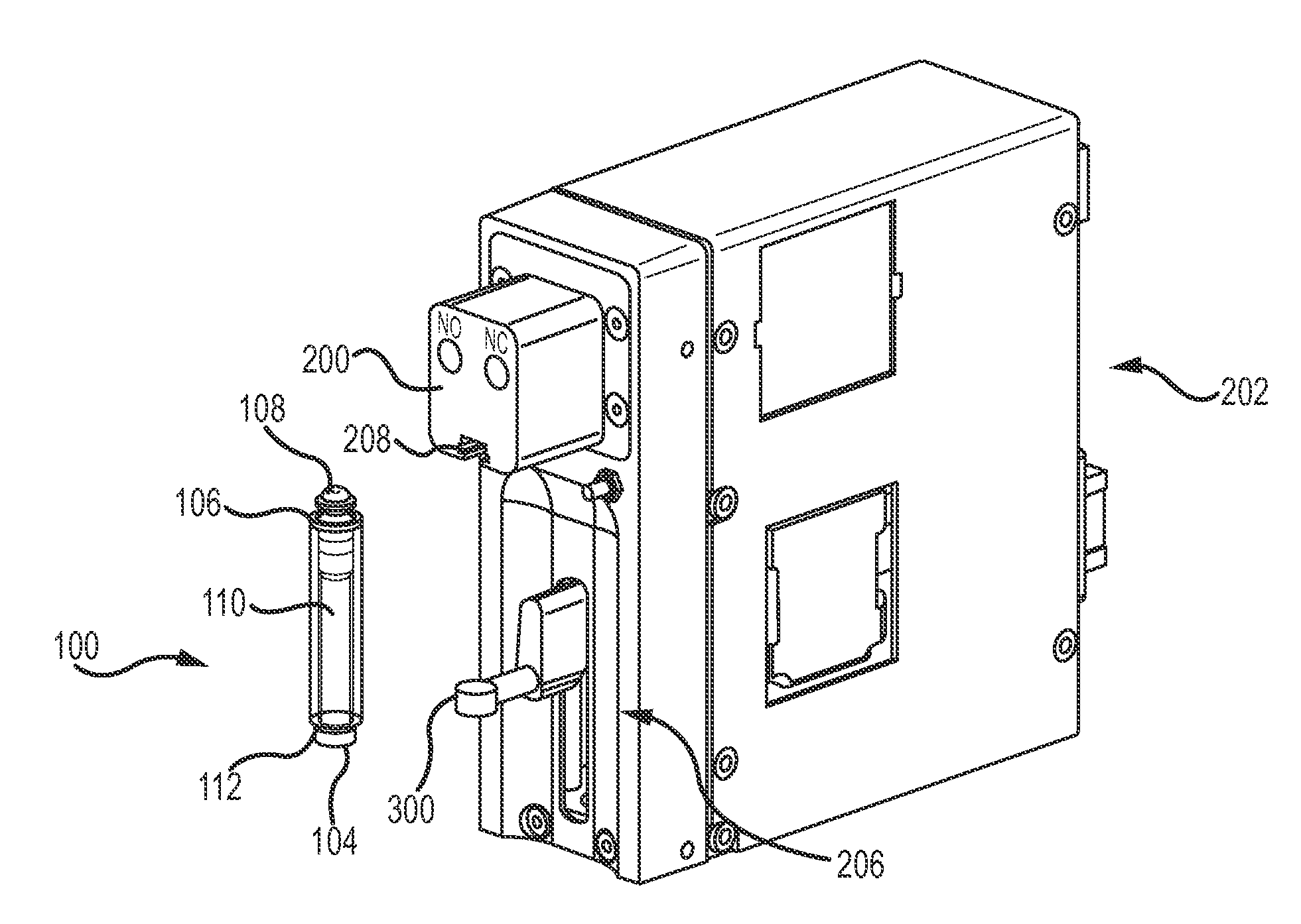
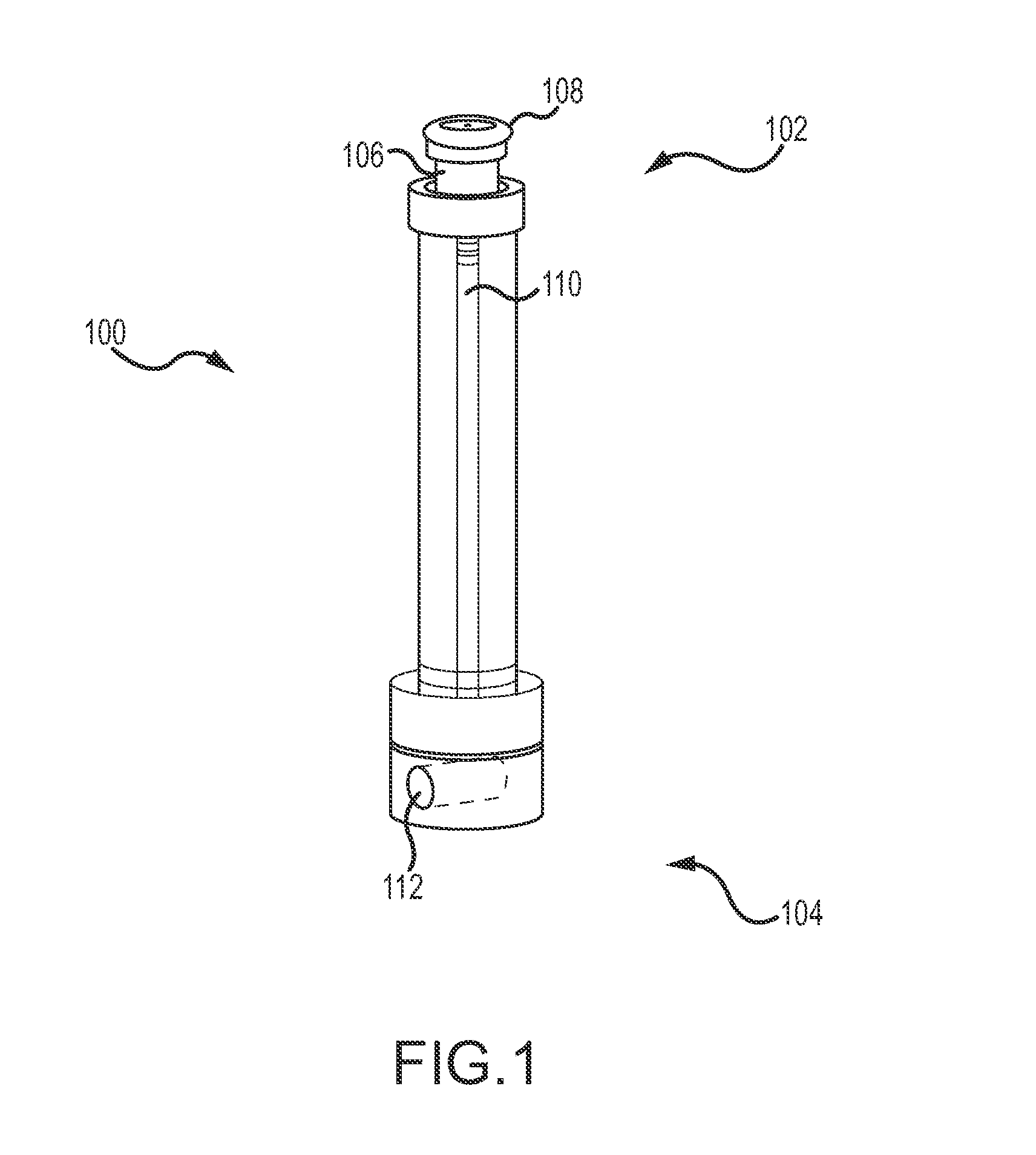
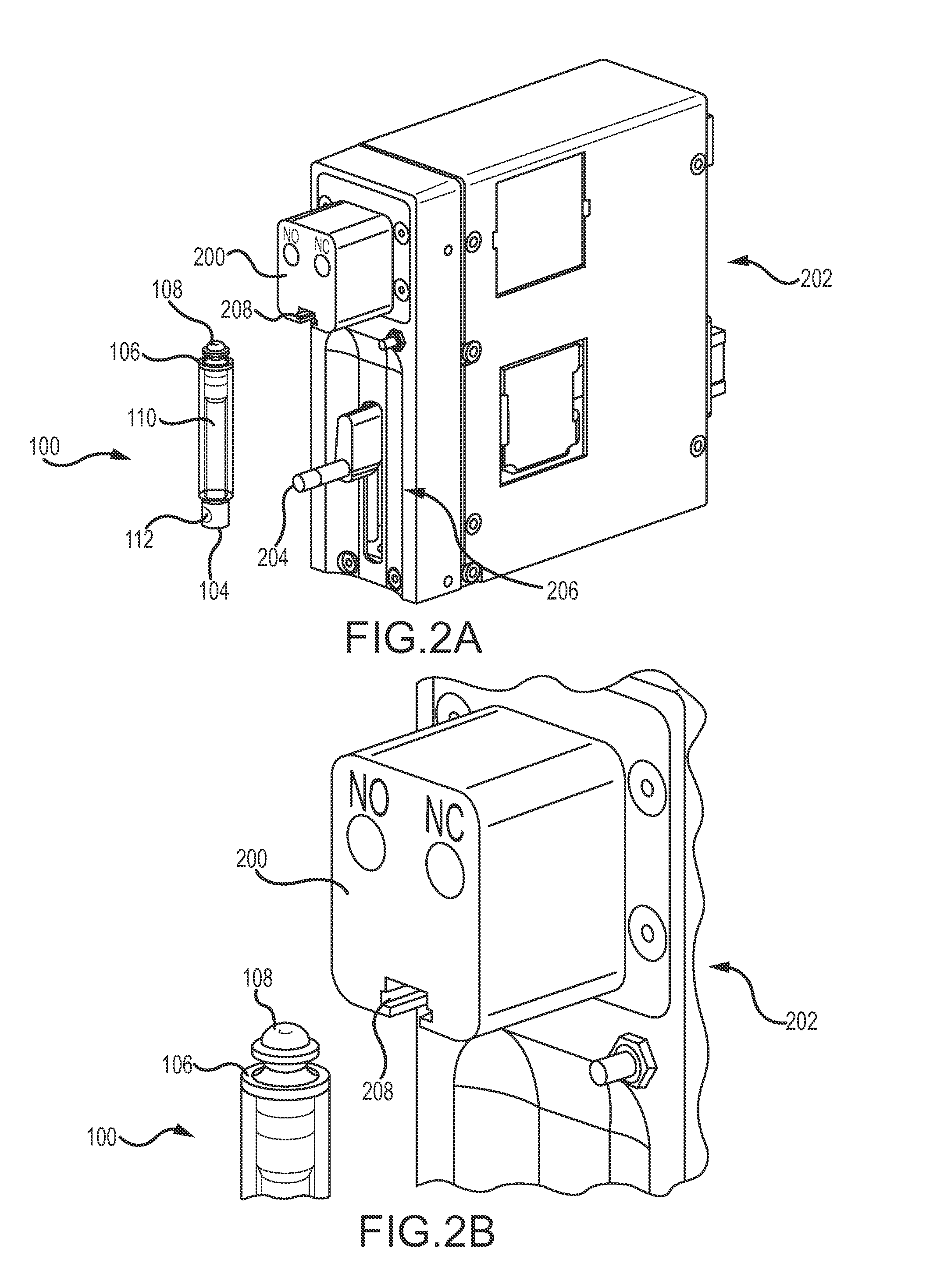
[0089]With initial reference to FIG. 1, a syringe assembly 100 is constructed from two main sub-assemblies: a barrel assembly 102 and a plunger assembly 104. The barrel assembly 102 provides means to mount the syringe assembly 100 to a syringe dock 200 (see FIG. 2), to, in one embodime...


PUM


Abstract

A fluid metering system having a syringe assembly attachable to a syringe dock is provided. The fluid metering system also comprises a plunger assembly with the syringe assembly that has a plunger configured to aspirate a fluid into the syringe assembly and / or dispense a fluid contained in the syringe assembly. A driving portion of a syringe drive with the fluid metering system is attachable to the plunger assembly, wherein the driving portion is configured to actuate dispensing and / or aspirating of the fluid. A slot with the syringe dock is configured to accept the syringe assembly, and an end cap with the syringe assembly slidingly engages the slot.

Description

FIELD OF THE INVENTION[0001]The embodiments described below relate to liquid metering, and more particularly, to an improved syringe quick disconnect interface and related methods.BACKGROUND[0002]Syringes generally include a plunger assembly that moves within a fluid bore. The plunger can draw in (aspirate) a fluid when the plunger is retracted from the bore and can dispense fluid when the plunger is pushed into the bore. Syringes are known for their precise fluid control and thus, have received great commercial success in the medical and laboratory fields. Typically, a syringe includes a single fluid port, wherein the fluid is drawn into and expelled from the bore through the port.[0003]Although the syringes can be controlled manually, they are often utilized with electronic syringe pumps to provide an automated system. Such pump systems generally utilize a lead screw or ball screw driven by a stepper motor to effectuate precise control of the syringe plunger's position. In the med...

Claims


Application Information

Patent Timeline
IPC IPC(8): F04B19/22F04B13/00F04B9/02
CPCF04B19/22F04B9/02A61J1/22A61M5/31533F04B13/00A61M5/1452A61M5/14546A61M5/1456A61M5/1458
Inventor SWEENEY, BRIANMORAL, LEONARDO DIEGOMIRANDA, ERIBERTOCASTRO, IAN KALANIONG, DICKSONNIELSEN, GARY
Owner NORGREN KLOEHN
Why Eureka
Try Eureka