Variofocusing monitoring shot and monitoring device

a monitoring shot and variable focus technology, applied in the field of optical technology, can solve the problems that the current use of surveillance televisions cannot meet the requirements, and achieve the effects of large imaging resolution, large range and zoom surveillance, and large field

Active Publication Date: 2015-10-15
HANS LASER TECH IND GRP CO LTD
View PDF3 Cites 0 Cited by
  • Summary
  • Abstract
  • Description
  • Claims
  • Application Information

AI Technical Summary

Benefits of technology

[0011]The present invention is able to perform a clear broad spectrum imaging by designing the shape and relative positions of various lens as described above. In addition to imaging through common visible light, it can perform clear imaging through infrared light. Thus the surveillance device using this lens assembly not only can get color images during surveillance of day time, but also can perform surveillance tasks at night with complete darkness environment to achieve all-weather surveillance. Furthermore, the lens assembly has an adjustable focal length and a large field of view variable range. The effective distance for surveillance can reach 0 to 500 m, which can achieve large range and zoom surveillance. Moreover, the lens assembly has a high imaging resolution, and each lens can be made of optical glass with relatively low cost to reduce manufacturing costs significantly.

Problems solved by technology

However, the currently used surveillance televisions cannot satisfy the requirements, and there is an urgent need to upgrade them.

Method used


Image

  • Variofocusing monitoring shot and monitoring device
  • Variofocusing monitoring shot and monitoring device
  • Variofocusing monitoring shot and monitoring device

Examples


Embodiment Construction

[0028]The above objects, features and advantages of the present invention will become more apparent by describing in detail embodiments thereof with reference to the accompanying drawings. It will be understood that the particular device embodying the invention are shown by way of illustration and not as a limitation of the invention.

[0029]Embodiments of the invention are described more fully hereinafter with reference to the accompanying drawings.

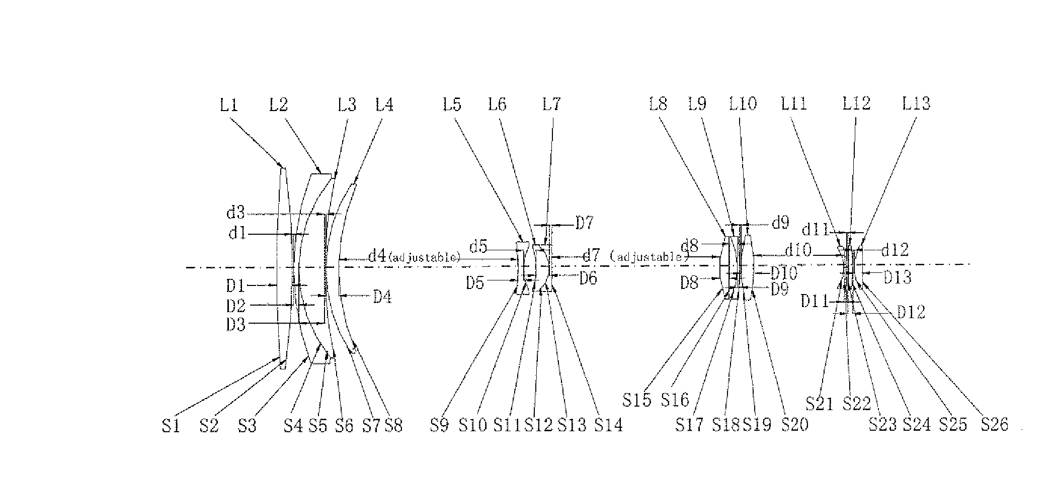
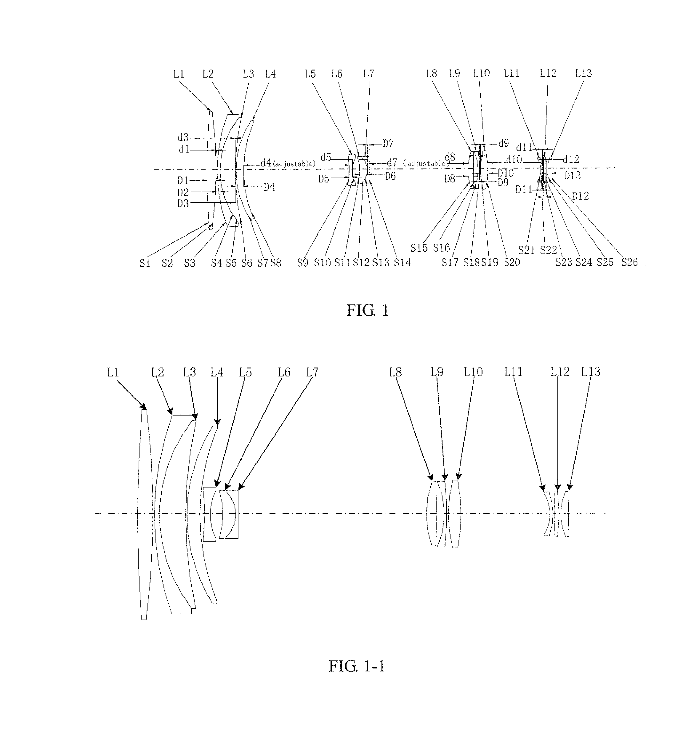
[0030]FIG. 1 illustrates a schematic diagram of a zoom lens assembly for surveillance according to an embodiment of present invention, only the parts related to the present embodiment are shown for convenience of description.

[0031]The zoom lens assembly for surveillance includes at least thirteen lenses, i.e. the first lens L1, the second lens L2, the third lens L3, the fourth lens L4, the fifth lens L5, the sixth lens L6, the seventh lens L7, the eighth lens L8, the ninth lens L9, the tenth lens L10, the eleventh lens L11, the twelfth len...


PUM


Abstract

A zoom lens assembly for monitor and a monitoring device are provided. The lens assembly comprises a first to a thirteenth lenses (L1-L13) arranged successively coaxially along the transmission direction of an incident light beam. The first, the eighth, the tenth and the twelfth lenses (L1, L8, L10 and L12) are biconvex positive lenses; the second, the ninth and the eleventh lenses (L2, L9 and L11) are falcate negative lenses; the third, the fourth, the sixth and the thirteenth lenses (L3, L4, L6 and L13) are falcate positive lenses; the fifth lens (L5) is a biconcave negative lens; and the seventh lens (L7) is a plano-concave negative lens. The second and the third lenses (L2 and L3) are closely adhered to each other, and the sixth and the seventh lenses (L6 and L7) are closely adhered to each other. The intermediate parts of the second, the third, the fourth and the thirteenth lenses (L2, L3, L4 and L13) are all convex toward a direction reverse to the transmission direction an incident light beam; the intermediate parts of the sixth, the ninth and the eleventh lenses (L6, L9 and L11) are all convex toward the transmission direction of the incident light beam; and the fifth, the sixth and the seventh lenses (L5, L6 and L7) can move synchronously along a light axis direction. The shot can realize all-weather, wide-range and variofocusing monitoring. The shot has a high imaging sharpness and a simple structure; and the cost of the material is low, thus controlling the manufacturing cost effectively.

Description

FIELD OF THE INVENTION[0001]The present invention relates to the field of optical technology, and more particularly relates to a zoom lens assembly for surveillance and a surveillance device.BACKGROUND OF THE INVENTION[0002]With the extensive application of surveillance television, there is an increasing demand on time and range of surveillance, such as the ability of surveillance day and night with protection from the weather and the need for larger scale surveillance to reduce the limitation of surveillance space. However, the currently used surveillance televisions cannot satisfy the requirements, and there is an urgent need to upgrade them. The function upgrading of surveillance device mainly depends on the improvement of the lens assembly for surveillance.SUMMARY OF THE INVENTIONTechnology Problem[0003]It is an object of the present invention to provide a zoom lens assembly for surveillance, thus allowing an all-weather, large-scale, and zoom surveillance.Technology Solution[00...

Claims


Application Information

Patent Timeline
Patent Type & Authority Applications(United States)
IPC IPC(8): G02B15/14H04N5/232H04N5/372G02B7/10
CPCG02B15/14H04N5/372H04N5/23296G02B7/10G02B15/143H04N23/69H04N25/71
Inventor LI, JIAYINGGAO, YUNFENG
Owner HANS LASER TECH IND GRP CO LTD
Why Eureka
Try Eureka